|
|
This topic comprises 4 pages: 1 2 3 4
|
|
Author
|
Topic: Refurbishing Altec Voice of the Theater Speakers?
|
Steve Guttag
We forgot the crackers Gromit!!!

Posts: 12814
From: Annapolis, MD
Registered: Dec 1999
|
 posted 09-06-2009 03:23 AM


Actually, yes! If you were to take as many plot points as possible; that is say, starting just below 500Hz...say 300Hz (you need not nor should you do this at High Power!). Use your generator and verify constant voltage amplitude at each frequency, measure the current in the system. Do this at many frequencies and then plot them on graph paper, you could come up with the driver's impedance chart.
Here is an example of what a typical response chart is versus impedance:
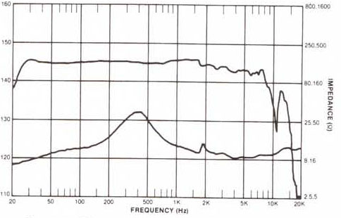
Note, this is a driver mounting just on a tube (for loading), not a horn. The lower line is the impedance and its values are on the right side of the graph. You'll notice that the value is rarely at the 8 or 16-Ohm mark. In fact, the driver impedance is typically the LOWEST it should be within its desired operating frequency range. Note too, near the crossover frequencies (500-1.5K, depending on the system)...that value may vary GREATLY. For the 16-Ohm version of the driver this plot was done for, it is at 50-Ohms!
Something may seem amiss...so lets put a horn on the driver and see what things look like:
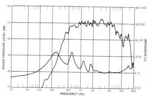
Now things don't look so smooth (welcome to reality) but also the impedance dropped near the crossover region. It is closer to 35-Ohms. So even your measurement conditions will affect things.
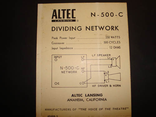
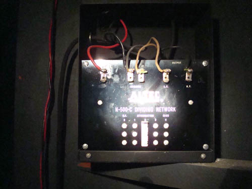
This is one reason why passive crossovers are so tricky to get right. A driver's impedance number alone tells one very little. One really needs to design the crossover around the intended speaker system including all of its components in order to get a smooth transition. The more generic the crossover is, the less likely it is going to fit any particular system. A great advantage to bi-amping is that you remove all of this from the equation. The frequency response of the electronics (analog or digital) is going to be much more uniform through the crossover region. Most passive crossover systems (though certainly not all) today are really just accommodation crossovers that protect the drivers...they rarely, if ever, provide for a smooth transition in either level or even phase. At least in yesteryear, many of the crossovers had multi-tap inductors to try and better match things through crossover and also some adjustability on the HF response. Nowadays, things are pretty much "preset." About the only way a manufacturer can do a spec sheet though is basing the frequency response on an anechoic chamber, which as zero resemblance to a theatre. Which is why what a speaker's response looks like on paper often differs when it is in operation.
Steve
| IP: Logged
|
|
|
|
|
|
|
|
|
|
|
|
|
|
|
|
|
|
|
|
|
|
|
|
|
|
|
|
|
|
|
|
All times are Central (GMT -6:00)
|
This topic comprises 4 pages: 1 2 3 4
|
Powered by Infopop Corporation
UBB.classicTM
6.3.1.2
The Film-Tech Forums are designed for various members related to the cinema industry to express their opinions, viewpoints and testimonials on various products, services and events based upon speculation, personal knowledge and factual information through use, therefore all views represented here allow no liability upon the publishers of this web site and the owners of said views assume no liability for any ill will resulting from these postings. The posts made here are for educational as well as entertainment purposes and as such anyone viewing this portion of the website must accept these views as statements of the author of that opinion
and agrees to release the authors from any and all liability.
|

 Home
Home






![[beer]](graemlins/beer.gif)

![[Smile]](smile.gif) Yes it is NOT the right way to fix the problem, BUT in a very rough sense it should help--a bit. Is it good enough to compensate for the mismatch? Maybe, maybe not. Obviously impedance varies with elements of frequency, inductance (and capacitance?) as well as simple resistance. And as Steve's post with the curves showed, it will vary with the acoustic load on the diaphragm as well.
Yes it is NOT the right way to fix the problem, BUT in a very rough sense it should help--a bit. Is it good enough to compensate for the mismatch? Maybe, maybe not. Obviously impedance varies with elements of frequency, inductance (and capacitance?) as well as simple resistance. And as Steve's post with the curves showed, it will vary with the acoustic load on the diaphragm as well. 


 Printer-friendly view of this topic