|
|
This topic comprises 2 pages: 1 2
|
|
Author
|
Topic: Planar PT-1545 Touch Screen monitor
|
|
|
|
|
|
|
|
|
|
|
|
|
|
|
|
|
|
|
|
|
Mark Gulbrandsen
Resident Trollmaster

Posts: 16657
From: Music City
Registered: Jun 99
|
 posted 01-20-2017 04:06 PM


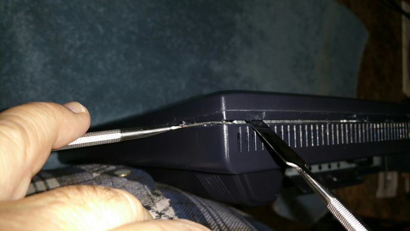
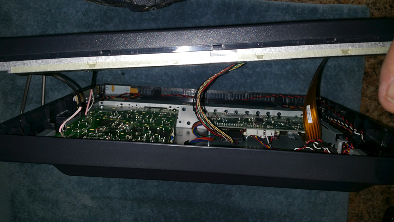
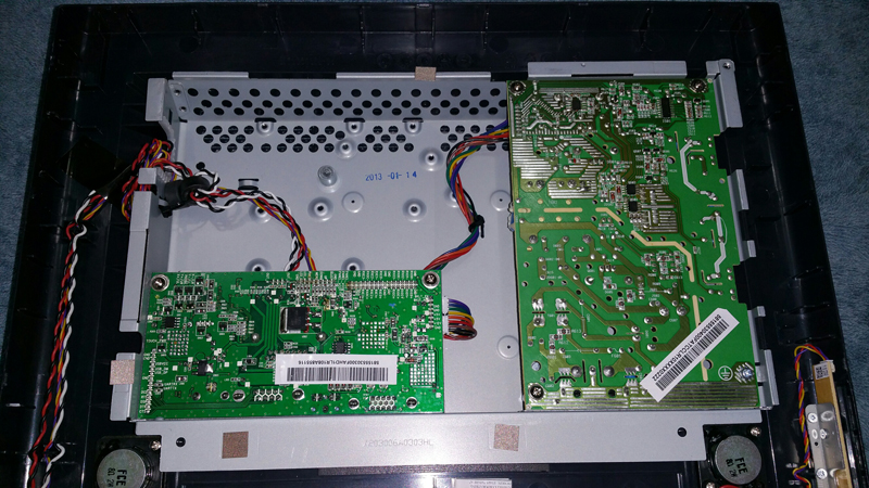
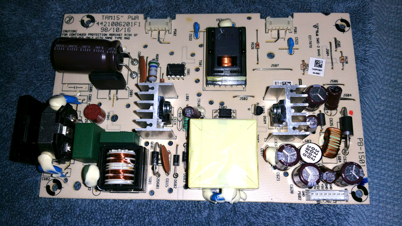
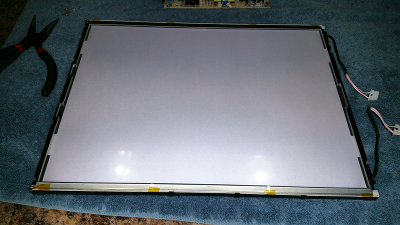
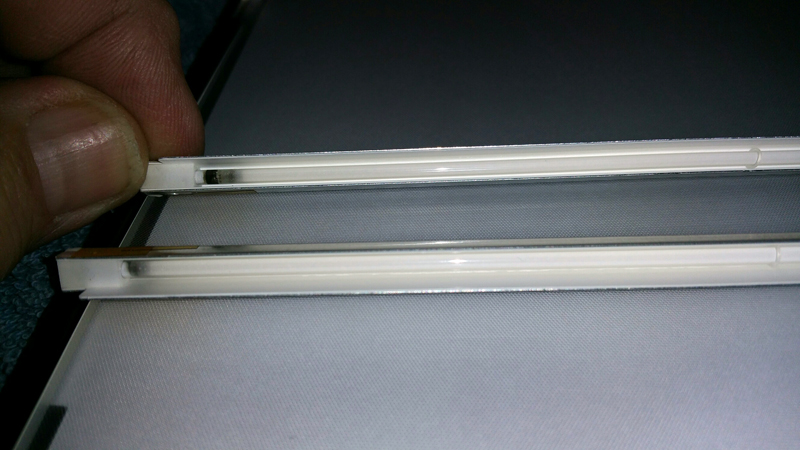
I just got a second dead PT-1545 going again. The lamps in this one were fine, the CCFL power supply was at issue. The power supply is a nightmare to trace, although the actual inverter itself on the ps board is pretty simple and more or less exactly the same as what is on a dual lamp replacement inverter board, tracing how it is control ed by the video input card is next to impossible. So the solution here was to hang another small inverter board on the monitor just to power the lamps. There is room in the internal chassis for a small board, however I didn't like the idea of extending the leads fomr the CCFL lamps over or near the low voltage DC supply. So I decided to outboard the supply and mount it to the rear of the monitor in a small plastic box which is on order. This process is about a two hour job, and not sure from a cost standpoint that I would do it again or not. It would be nice and easy to be able to mount the new board to the rear of the LCD display itself and just sandwich this back together. However there is only about 2mm spacing between the boards and the rear of the LCD panel. I may consider extending the lamp leads to the rear chassis area on the next one, but the ignition voltage of these lamps is about 3kv and the run voltage is a few hundred, so its gonna have to be well insulated, and the two leads should be kept separated. Here are a few pictures. The board plugs in to both power source and the lamps.
The flying yellow lead is brightness. High brightness it gets tied to +5 volts. Low brightness to ground. Just going to leave this on medium brightness.
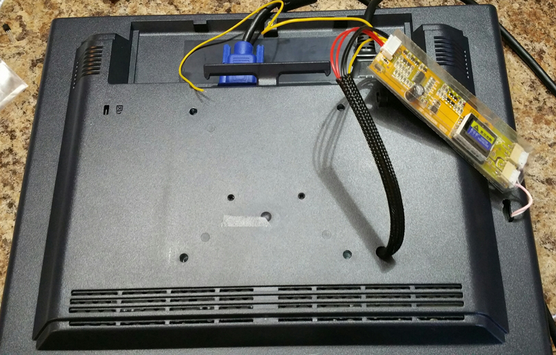
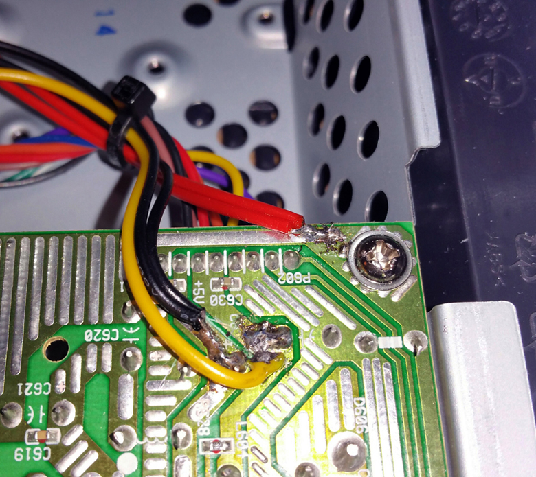
A fairly long wiring harness what has wire with crappy insulation on it is included with each board. You have to tack it to these locations. Ground, +12 volts for the board supply and + 5 volts to turn the board on.
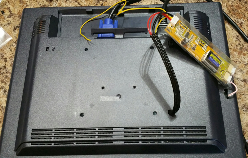
The board will mount along the right rear of the monitor in a vertical position. one toggel switch to turn the lmaps on or off. A 3 volt relay could also be used if you want to, as there is a switched 3 volt supply on the video card. The main power supply is an always live type. I am just going to put a small toggle switch on the plastic box to turn the lamps on and off.
The key to these boards is getting one with 8mm pitch CCFl lead sockets.
| IP: Logged
|
|
|
|
|
|
|
|
All times are Central (GMT -6:00)
|
This topic comprises 2 pages: 1 2
|
Powered by Infopop Corporation
UBB.classicTM
6.3.1.2
The Film-Tech Forums are designed for various members related to the cinema industry to express their opinions, viewpoints and testimonials on various products, services and events based upon speculation, personal knowledge and factual information through use, therefore all views represented here allow no liability upon the publishers of this web site and the owners of said views assume no liability for any ill will resulting from these postings. The posts made here are for educational as well as entertainment purposes and as such anyone viewing this portion of the website must accept these views as statements of the author of that opinion
and agrees to release the authors from any and all liability.
|

 Home
Home








 Printer-friendly view of this topic