This is topic New Analog Sound Readers in forum Film Handlers' Forum at Film-Tech Forum ARCHIVE.
To visit this topic, use this URL:
https://ft-forum.com/ft/cgi-bin/ubb/ultimatebb.cgi?ubb=get_topic;f=1;t=001243
Posted by Bill Purdy (Member # 202) on 07-28-2000, 02:44 PM:
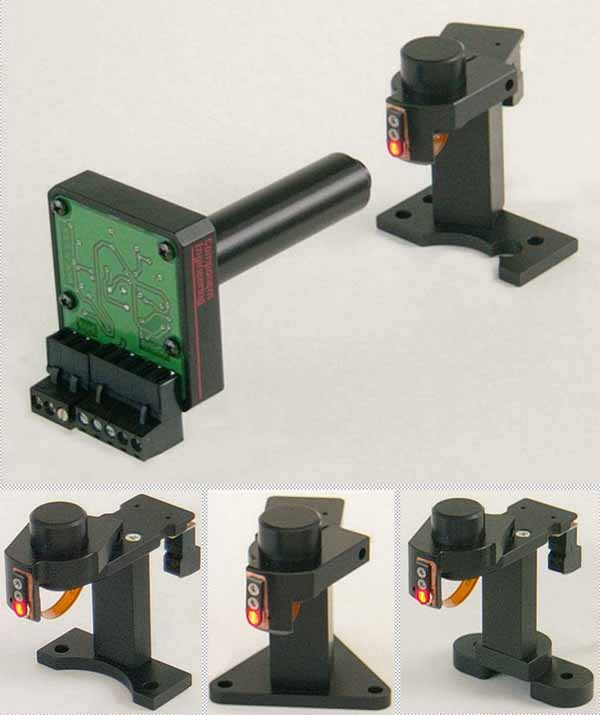
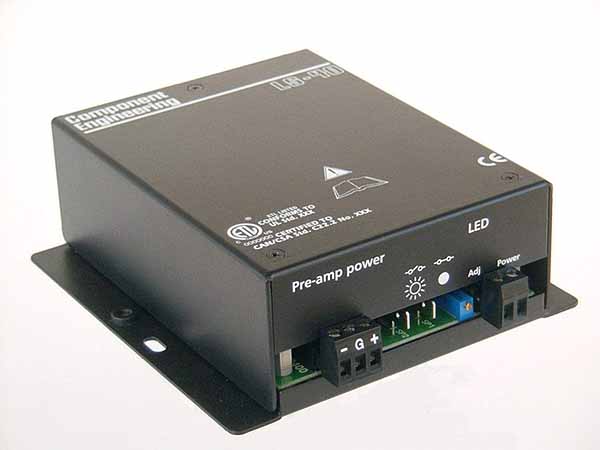
We are just starting production on a new line of low cost analog only sound readers for Simplex, Century, RCA and Ballantyne Model 7 sound heads. The idea is that if you have to change your heads to accomodate the cyan sound tracks, why not do it right and increase the quality of your sound at the same time?Therefore, we are offering these readers (called "ASR-40") which feature not only 660 nM red LEDs, but with geniune reverse scan and a nifty little low noise power supply. Pricing will depend upon your supplier, but in general they are a full 30% below our standard readers. This means that these kits are only slightly more than the cheaper solution, but you get so much more for your money.
Small quantities will be available later in August. Should you want to know, all of our existing readers, analog and/or digital will still be available.
For those of you going to ShowEast, please come by booth 1500/1501 and you can fondle them.
What else would you like to know?
------------------
Bill Purdy
Component Engineering
Posted by Ken Layton (Member # 133) on 07-28-2000, 02:56 PM:
You left out Motiograph SH-7500 soundhead.
Also will your new RCA kit fit the 1040 without carving up the castings?
Posted by Barry Floyd (Member # 385) on 07-28-2000, 03:27 PM:
RCA 9030's ?
Posted by Mark Gulbrandsen (Member # 72) on 07-28-2000, 03:42 PM:
Yes Barry!! Check out the pictures on our web page. www.getgts.com
Mark@GTS
Posted by Kevin Crawford (Member # 469) on 07-29-2000, 12:09 AM:
Not to sound like a crazy guy, but.....What makes these different than your most recent readers? Aside from the price difference
Posted by Bill Purdy (Member # 202) on 07-29-2000, 10:41 AM:
To answer Ken, Sorry about the Motiograph, and yes, you still have to exercise your sawzall in order to install one in a 1040. The reason is essentially the same for both of them and it is driven by the focal length of our standard lens. The lens focal length determines where the box containing the photocell has to be, and for these heads there is stuff in the way. The REAL reason is basic Economics 101. Volume buying saves a lot of money. We buy a lot of these lenses, enough that we can have them made to our wishes. While this is good, it means that we cannot afford to have more than one type in stock (we actually have two, but the other ones won't help in these cases). We recently had some samples made for a future issue, and they were 15 times the cost of our standard parts. So, with the Motiograph, one would have to remove that whole exciter lamp/lens bracket assembly which you can't do without removing the picture head, sawing chunks of the bracket out of the way and re-assembling with the reader head in place. The LED end would not be a problem. You can get the reader head into the RCA, but, yes, you still have to carve out that little vent baffle and remove the subassembly in order to get the lens and the adapter sleeve into the lens mount. At least you can do it without taking the whole projector apart.To Kevin, while we have managed to keep what we consider to be the factors important for a quality component, we have been able to save a lot of money in several areas. The power supply is an example. It is not a plug-in system which means no extra mounting package (but all of the connectors on the new one are unpluggable). Because we abandoned the requirement that it fit into a 1U rack space we could use off-the-shelf trasformers instead of the expensive custom one in the standard unit. While the pre-amp circuitry in the reader head is the same (actually, slightly better), it is much less expensive to buld. There is only one layer of circuit board instead of two. There is no internal lateral adjustment. Because of the quality of the lenses mentioned above, we no longer have to set the exact magnification of each unit as is done on the standard model. We have studied this enough to know that the lens tolerances are good enough that we can press all the parts together and after a quick check it is ready to ship. This saves a lot of expensive labor. On the other hand, we kept all of the sturdy machined housings. We kept the plug-in connections for ease of servicing. We kept the solid copper LED mounts for the best heat transfer. These mounts are also fully adjustable so that you can maximize the optical alignment. These two factors alone can mean greatly increased LED life. Speaking of increasing LED life, the power supply has in it a thumpless On/Off circuit so that you can turn them off between shows. That's the sort of stuff.
------------------
Bill Purdy
Component Engineering
Posted by Scott Norwood (Member # 30) on 07-29-2000, 10:55 AM:
How much is the upgrade for the RCA-1040? How painful is the installation? I have a 1040 here that's in great condition and which runs beautifully at home.
Posted by Mark Gulbrandsen (Member # 72) on 07-29-2000, 11:56 AM:
Guys, The Kelmar AT-1277 retrofit goes right in to the SH-75000. No sawing necessary. No need to remove the picture head to do it. You do need a right angle or very short screwdriver though. A socket wrench with a screwdriver blade also works for removing the exciter lamp holder upper screw. I guess the difference here is that the back end of the Kelmar unit is rectangular and clears the area on the casting where the exciter socket goes. I can see with the C.E. and its square end that it may not clear the part of the casting where the exciter socket mounts. But either way the C.E. should also work easily by just sawing that part of the casting off, about a 2 minuite thing at best. The focal length is the same for the Motiograph as for a Century/Simplex. No reason at all it shouldn't work out. What do you think Bill?
Mark
Posted by Dave Bird (Member # 490) on 07-29-2000, 12:02 PM:
Sorry again for the basic questions. I've been away from my projectors for a few weeks so have made NO progress. I can sort of see what these new sound readers equate to in my SH-1020's as far as light and lens. Is the transformer pictured simply the replacement for my "DC exciter lamp power supply? Will these LED's reproduce sound on older film? If so, is there any sense even installing the old exciter's (I probably will anyway to learn)? Thanks. PS- SH-1020's???????------------------
Dave Bird
Posted by Jeff Stricker (Member # 224) on 07-29-2000, 04:00 PM:
I know this is a real basic question to those in the know. But what is the pick up element used to read the red LED wavelength? Is it a photo transistor, photo resistor, or plain old silicon solar cell, or something else? Thanks in advace!!
Posted by Josh Jones (Member # 447) on 07-29-2000, 11:20 PM:
I thought they were CCD's but not sureBTW does anyone have any Gaumont Kalee proj pix? never seen an operational one
Josh
------------------
"where to they teach you to talk like this, in some Panema City wana hump-hump-bar? sell crazy someplace else. we're all stocked up here" As good as it gets
Posted by Dustin Mitchell (Member # 372) on 07-30-2000, 01:40 AM:
Basic question for yah from a sound-dumb guy. So with these readers there is no sound drum? Does the film just pass through the light?
Posted by Bill Purdy (Member # 202) on 07-30-2000, 09:35 AM:
From what I am reading from some of the questions, there seems to be a lack of understanding of how this reverse scan system works. OK, for most of us who make these things, here's how. Dolby Laboratories has had made the two essential elements for this system, and we all buy them from Dolby. One is the 660 nanometer red LED which is now the light source for both the analog and the digital readers. The other component is the receiving cell. This is a variant on the silicon photovoltaic "split" cell now used in almost all sound heads. This one consists of a very different configuration whereby there are the two cells separated by a very narrow septum and with a slit mask deposited right on top of the cell surface. What happens is that the red LED illuminates the sound track and the lens images the track onto the face of the cell. It is literally projected onto the cell. Because the image is magnified (about 3.6 times) the effective slit width is very small. Because the masking takes place on the surface of the cell there is essentially no cross talk and this in turn is why the stereo decoding is so perfect.
Because the LEDs are nowhere near as bright as an exciter lamp, a pre-amp is required and that is what is built into the box at the end of the lens tube. Its output emulates the signal that would be coming from one of the original open cells. This is why the new readers should interface with all of the other processors. This pre-amp requires bi-polar DC current which is generated by the power supply which also, of course, supplies the current to the LED. In the case of our power supplies, the output to the LED is current regulated and the no-load voltage is clamped to a safe level should the LED be connected backwards (the LEDs from Dolby may come with either polarity).
I am sorry that the pictures may have given the impression that there is no sound drum....there most certainly must be. The pictures were taken to show only the parts of the kit. If you go to our website, "www.componentengineering.com" under Sound Reader you will see several pix with all the parts (including digital) in place. There is even a picture of at least the sound head portion of a Kalee.
To Scott, the installation in a 1040 is slightly painful. The lens tube on the front of the pre-amp box is too long for it to be inserted into the slit lens clamp. The rear wall of the sound head is too close. Therefore, you have to remove that whole subassembly, stick the lens and its adapter sleeve in place and then put the assembly back in. Even then, when you try to focus it, the pre-amp box may want to be in the space occupied by that piece of cast iron in the upper left hand corner which is a light baffle over the ventilator slot. If you don't mind butchering the whole back end of the sound head you could just cut it away and both problems would be answered.
------------------
Bill Purdy
Component Engineering
Posted by Jeff Stricker (Member # 224) on 07-30-2000, 10:14 AM:
Many thanks for your response and all the details, Bill. My question involved the receiving cell, which you indicated is a type of silicon photovoltaic cell. That clears up a nagging question I've had for some time. The lower output due to red illumination, however, necessitates the need for amplification right at the pick up instead of a distance away as in older systems using white exciter lamp illumination. Having amplification right at the pickup, of course, will improve the signal to noise of the system.thanks again! Jeff
Posted by Gordon McLeod (Member # 33) on 07-30-2000, 01:03 PM:
Bill a question that has always nagged me
A silicon photovoltaic cell exhibits it lowest distortion when it is used as a current source not a voltage source. This was documented many many years ago by bang and Olfsen and several companies introduced current based preamps that in effect have thecell reflect into what is in effect a short circuit
Why has a preamp not been utilized for the newer reverse scan reader that utilised this principle. The reverse scan have inherintly exhibited higher levels of distortion due mainly to the red light and silver tracks but the preamp/cell issue keeps making me think that might also be a source
Posted by Robert Throop (Member # 61) on 07-30-2000, 01:21 PM:
We are now in the process of installing Kelmar reverse scan readers in a pair of RCA MI1050 soundheads. By detaching the preamp and mounting it on the back side of the soundhead the need for cutting is eliminated.
Can this also be done with the CE reader?------------------
Bob Throop
Posted by Mark Gulbrandsen (Member # 72) on 07-30-2000, 03:12 PM:
Gord, Are you sure its not a current converter? I seem to remember Sam Chavez saying that it was ment to be used that way.Bob,
Thats what Christie does for their projector scanners. The Preamp is removed from the scanner assy and is attached by a short length of shielded cable. The preamp is mounted on the frame of the projector right behind the scanner.
I am making an analog scanner for a AA_2 right now that will utilize a Christie reader cause it has a short focal length lens that allows it to fit on the original casting...although the casting requires some re-machining to mount it. I also have to make a new LED mount as well.
Mark
Mark
Posted by Gordon McLeod (Member # 33) on 07-30-2000, 04:00 PM:
The cell is a current source the first stage of the preamp is usually a current to voltage converter such as a transconductance amplifier
Panastereo, Kintek and a Mono system called the System from LP Associates used this for their input stage
Posted by Kevin Crawford (Member # 469) on 07-30-2000, 06:29 PM:
BillHave you guys thought of a way to keep oil out of the lens assy on the readers.
There is one theatre I do that never uses a rag to clean out the machines. Oil everywhere. I have replaced at least 3 analog and two digital readers. Mind you it only has 5 screens.
Posted by Daryl Lund (Member # 356) on 07-31-2000, 10:55 PM:
Why can,t CE co make somthing to replace the slit lense so you wont have to cut the crap out of the older models.
Posted by Bill Purdy (Member # 202) on 08-01-2000, 12:06 PM:
Gordon, you are correct about the photo-cell and this is why the pre-amp in the sound head does just what you are asking for. I am not enough of an electronics theoretician to be able to explain it fully, but the net is that the cell looks into the (-) input of an op-amp and the feed back network holds that node very close to ground so that there is no effective voltage----just current. As the circuit of the pre-amp is Dolby's, I am reluctant to publish it without their permission. I think, note that "think", that the distortion you refer to is a function of cross mod artifacts which is one to the purposes of the "High Magenta" tracks.As to the matter of the removeability of the photo cell etc., Our design philosophy from the beginning has been that it was our responsibility to provide an assembly that has been properly adjusted for magnification, track placement and all that sort of thing. Yes, there are those out there who are fully capable of doing this properly, but there are a lot more who are not aware of all of the factors to be considered. So, we build them as an assembly that is clean, dark and not easily damaged.
------------------
Bill Purdy
Component Engineering