
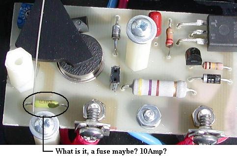
Does anyone have a schematic for these controls?
I have confirmed that the mystery device is indeed a 10 amp fuse.
The SCR is a NTE-5460.
The device under the light shutter and above the cadium cell is a LM-334, and crosses to nothing! What is it, and what is the substitute?
The device to the right and just under the SCR is a Silicone Unilateral Switch Thyristor Trigger. It crosses to a RCA SK7900.
Thanks for your inputs.
------------------
Samual Hunter Sr.
KC5ZSL
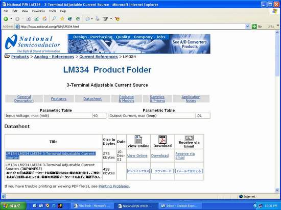
The link http://www.national.com/pf/LM/LM334.html
------------------
Samual Hunter Sr.
KC5ZSL
The phase control repair info and schematic is already here on the manuals page under "Field Bulletins" -> "Strong Phase control adjustment and repair info".
The LM334z is a constant current source (Mouser number 511-LM334Z) and for the SCR, I use Mouser number 519-S6020L (isolated tab). As to your mystery component, it is a 10 amp pico fuse (Mouser number 5761-51010).
 So I had to reverse engineer it.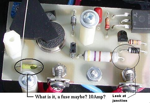
------------------
Samual Hunter Sr.
KC5ZSL
I downloaded the schematic. 1N4004 does appear to be reversed biased, but I think that is the way it is supposed to be. It looks like basically it is in series with the LED and the LM334Z, which would serve as a rectified AC source for the 3-volt LED. Maybe the Zener is used to prevent inductive spikes from the motor from trashing the SCR. (just a guess)
Anyway, I put in a new NTE SCR and a fuse. Apparently they were destroyed when the wire fell off the pin plug while it was in the spindle and shorted to ground.
Installed the newly repaired Phase Control on a CFS Super Platter, and I was very pleased with the results. I observed an average of a slow 90 degree oscillation of the pay-out, which was far superior to the 360 degree over-shoot and a 360 degree under-shoot I have been seeing with Micro-Switches. Because of the 10 Ohm 25-Watt resistor that shunts the entire shebang on pay-out, It made the Strong A-3 look like a POS!
(Sorry, Pat....but tell your platter guys to put that resistor in place. They don't use it in the A-3. That is one of the reason for major over-shoots and under-shoots of the A-3 when they are converted to Micros. The motor is either OFF or ON! With the 10 Ohm 25-Watt resistor in place, it is a "Soft Off" for a slow run-down, and then a "Soft ON" for a slow ramp-up.) The results? No whipping of the platter, and no tossing of prints. Ask your platter engineers to make improvements - they are needed to stay competitive with folks from Christie, SPECO and Kineton. 
Now you know why a CFS micro-switch platter out-performs an A3 with micro-switches. This should breath new life in the old Super Platters some of you guys hate so much. Between the two, I would prefer a 20 year-old Super Platter with Phase Controls over a Strong/Potts A3 with Micro switches. The proof is clear from my observations this evening. (I particularly liked the "Ooooo's and Ahhhhhh's" from the operators when they seen the results of the Phase Control.)
Sam, I was eyeballing that junction as you have shown. I think Ken was using "Instant Polarities" that apparently throws confusion into the works. However, Ken's schematic is correct.
 .
.Here is your request:
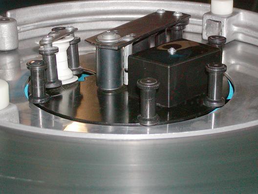
Damn...How did Poopers (my Beagle) manage to get one of his hairs by the angle roller? Poops done right. He sniffed it and gave it his approval. At least, his "deposite" was not something else that is usually accompanied with a SNORT!
I will post a schematic on Monday when I can scan it in.
Rick
On start-up the elevator does its normal wild things, but when it finds its null within the first 10 seconds or so, it runs like a champ.
Please - don't anyone else make that adjustment on the trim pot until Rick answers. There might be a better way.
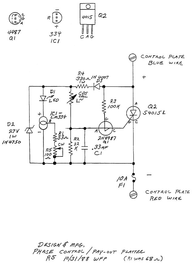
Hope this helps
Rick
This could be relatively easily retro-fitted in the field, as the resistor could be mounted inside the arm and a couple of short leads soldered to the phase control lines.
Your thoughts are the same as mine for the A-3 modification. I will do that mod with my A-3's in Anacortes when I get a chance, although I have micros in the pay-out heads. Another nice thing about the resistor's presence is that a smaller micro-switch could be used instead of that big heavy one being used now. Remember the old Potts and CFS platters used a 3-amp micro-switch you could get at Radio Shack? They ran for years, until someone had the motor switch in the wrong position during build-up, and burned up the resistor. Then the micro-switch would be toast in just a few "clicks".
However, a good idea would be to try a couple modifications first and see how it goes in the long run.