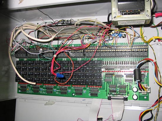
Also, he would like a diagram of the terminal strip. Primarily, he needs to know where to reconnect some loose wires from the cue detector/failsafe.
Please email whatever you have that might be of help.
~Manny (The New York Times Bestseller!)
I will check it out and report back whether they are indeed the same.
Inside the actual CA-21 there is a long row of screw connectors across the back of the motherboard marked RY-1 thru RY-40 (these seem to be relays) and then I-1 thru I-24 (I'm guessing these would be inputs).
We need to know what goes where. We know enough to know that these are connected wrong, but we don't know what would be right.
In particular, we are trying to connect a Component Engineering FM35 Cue Detector/Failsafe to the Christie/Pennywise CA-21 Automation.
Brad (or anyone who knows)...Is the CA-21 a "two piece" automation? We have the actual CA-21 automation, but all indications are that there should be a second part with relays and terminal connections. Alas, we don't have that second part; the CA-21 is wired up so that it triggers the relays in the old automation (in the ORC console).
Here is a picture of what I am trying to connect to:
I found the original manual that came with these and so now I know what the relays and inputs are for. I have tidied up the wires somewhat and this led to the elimination of a lot of them because they weren't actually being used. Everything seems to be in order now and the cue detector -- which was part of the original problem -- is working just fine now.
New problem:
The first run after turning the power on is aborted after about 8-10sec. The display reports a "lamp failure" (LFL) but we are not using that feature and nothing is connected to that input. All subsequent runs are uninterrupted.
How could turning the power set up the conditions for this problem? Any ideas?
I think that your eproms are set so that if the LFL kicks in and you restart it anyway that it overrides it. Pennywise is great about making custom eproms for people and that's probably what someone requested at some point.
Please photocopy that manual and send it in to us for others. 
I noticed that the Setup/Configuration manual for the Console Mount version is not in the manuals section. What gives? Isn't that your model?
The point of that question: I'm curious as to whether the console mount version looks the same inside? All those little screw connectors, I mean. I have six of them but I'm not working out at that location for a while and a simple "yes" or "no" would satisfy my curiosity about that.
Also, if I were to get the interface board, what connects to it? I see a couple of connection points for two ribbon cables on the backside of the keypad board. Is that how this is done? I guess I'm seeking clarification as to whether the Wall-Mount version is designed to work with the interface board?
By the way...Thanks for the suggestion, but placing a jumper in the Xenon input did not work...I got a LFL every time* after I did that. Your suggestion did, however, inspire me to work around the LFL problem by feeding the FM-35's "Motion" detector into the Xenon input (I-8) on the CA-21 and THAT worked.
~Manny.
*I was tempted to write a very "tongue-in-cheek" lampoon of that suggestion but I don't know what your sense of humor is like and I was afraid it might have backfired.
Anyway...here goes...
quote:
Dear Brad:I was misguided by your careless suggestion. Instead of a lamp failure on only the first run, I started getting LFL errors every time. I would type more, but my jaws are aching.
~Manny (I can't believe I ate the whole thing).
I don't think there are enough smilies in the world to give that the intended (humorous) tone.
quote:
"If memory serves, it is #61 and 62 on the "Bevan board", but yours is obviously different."
You DID double check these connections, right? Since yours is so different it may have required a different hookup. However getting a signal of motion from the failsafe vs. having a jumper there should produce the same results, so something sounds screwy there. Anyway, glad you got it running.
IIRC the gentleman from Pennywise told me that they are in the habit of keeping the Xenon "warm" (lower current) between shows...I assumed he was talking about Australia (anyone verify/deny this?)...maybe that's why it only looks for a Xenon input the first time (...and maybe not). I may have gotten that all wrong (this was in 1998) but anyway, it's solved now.
As for which interface board...I will clarify: there ain't no interface!
Here's what we discovered. The relays in the old ORC automation are being driven by the CA-21. It's a mess of teensy-weensy little wires soldered here, there and everywhere.
This will all be changed out as soon as I am done with current projects.
Thanks again for the help.
It has been 1542 days since the last post.
It has been 382 days since the last post.
quote: Brad MillerThis automation isn't mine, and isn't here.....it's from mine friend, he just need automation of cinema like projector start, lights on/off, curtains open.....and connect that to standard system now what is made with pushbuttons mostly....
The CA21 is the most versatile automation out there, but you have to know what you are doing and so far you haven't given us anything worthwhile to assist you with.
quote: Brad MillerHi Brad!
Oh boy, you have a pre-CAPIO model. Is it revision A, B, C or D? Also is there anything else at all written on that eprom label? Do you have any idea what theater circuit it came out of?