
Strong Highlight II console
Simplex Millenium with 5-star
TA-10 automations
10-plex
The complaint: Projector motor will not start when the green button is pressed. The lamp starts, and 7 second later, the change-over opens.
Motor always starts when manual switch is activated. (Leeson).
Simple, relays right? Nope, exchanged those, symptom still remains.
"Sweated" the joints on the start button with an iron.
Re-aligned lower roller to assure good purchase on FM-35.
By-passed motion and presence fail-safe along with platter wrap fail-safe. "God himself cannot sink her" - It sunk.
Wiring is good. (checked twice).
Cold solder joint on back of board? Shook and banged the hell out of everything during auto operation. If a cold solder joint should have heard the motor kick out. - nothing
(This, of course, is one of those calls where I could not make the fault happen till the second call, then ONCE out of a dozen times I confirmed it.)
Okay, so not relays then, obviously something in the timer-drive circuitry right? From a spare board, replaced the 4 on board chips. I tried it with an old trailer a dozen more times. Started every time.
It worked great (even with fail-safes "armed"), for two nights. Then tonight, got a page. Damn thing failed again.
Should I advise them to call an exorcist?
Second thoughts : It might well be that a buffer board is required here. Maybe the xenon striking is knocking out the motor signal, but the usual effect of xenon interference is to "reset" the automation, not to kill just one function.
First, check to see if the relay actually closes. If the relay does not close, check to see if the closure voltage to the relay "got lost" somewhere. If the relay does close, check the traces on the printed circuit board for an open trace on the motor feed circuit.
If this problem has been since "day one" - there could be program error.
If it was an interface error, the motor would not start manually, so I don't think it is that type of an error.
This automation has been working perfectly for the last five years. Then suddenly (and not every time either) this problem occured. Good point tho, if I can find long enough arms to reach around. Could solder a couple of wires to the green starting switch, i guess. It is a bitch being the only one on site with this type of call. Of course the intemittancy of this problem makes it even harder to trace. What do you do with an automation that works perfectly only when you're in the booth. Hang your picture near it?
Tried the ID's, shows up correctly on the remote status. Interesting point there tho, havent tried starting remotely with it. Hmmmmmmm.
I did first try to replace the relays. The problem still happened. For some reason tapping on the relays when ever this problem occured seemed to fix it. This only happened on 1 of 9 screens and only every once every few months with tapping on them.
Before that it would happen every other show.
I doubt it's a logic fault with the TA10 itself as event one and two are working correctly, its much more likley to be a mechanical fault, relay or the socket.
There is one thing you could do if this is becoming a real problem for you and you need to sort it in the short term. It's not a repair but a work around ....
The utility relay can be changed to a 'motor run' relay and duplicate the function of the motor relay itself. It's quite easy to do by cutting a trace and adding a jumper wire between two solder points. It's not actually detailed in the manual but is easy enough to work out. This would allow you to run for a while and see if the problem is still there. If it is, then its a logic problem, or xenon strike problem if not then its a relay problem.
The shield board that is available works a dream, its not expensive and worth a try. I have them in all my shows as we had problems with the xenon strike.
Regards Ken.
However, I seriously doubt it because the wave-soldering techniques used today are more superior than ever before. I would accept the bad relay or its socket theory if the traces are intact.
if it is in fact down to current and the contacts degrading... god knows how long the manual switch will last. As I'm sure you know the manual switch does not control the relay but carries the switch load directly. These are very simple low current switches and may only be in the region of 5amp rating... I can't find the info right now but I doubt if the curcuit was intended to carry that much current directly.
As he has a number of other screens that are working just fine it sounds more like one of the problems already talked about and is simply a mechanical failure of the relay or socket or dry solder join.
Faults like this are a nightmare if you can't get it to repeat the fault to order. I have a problem with one of my TA10's that every now and then decides not to 'see' any cue's. The FM35 'reads' the cue but the TA10 ignores them.... It's been a number of weeks now what with swapping components and testing....
Don at CE is a great help but its a time consuming process so I hope he's prepared for the same. Worst case senario is he replaces the main board with a service replacment, it's not so easy from London!!
quote:
Paul,
if it is in fact down to current and the contacts degrading... god knows how long the manual switch will last. As I'm sure you know the manual switch does not control the relay but carries the switch load directly. These are very simple low current switches and may only be in the region of 5amp rating... I can't find the info right now but I doubt if the curcuit was intended to carry that much current directly.
Right on! There are alot of old and new power-hog motors out there running projectors. Ever noticed how heavy the manual switches were on the old RCA (Robbins&Myers) and Simplex (Leland) motors?
Inductive loads are not the most friendly type loads on under-rated contacts in switches and relays.
It is like cramming 10 pounds of crap in a 5-pound bag. It won't hold it for very long.
Thanks for that Paul!!
Oh by the way Paul... love the white wig.... i know a bar where you'd go down a storm....

I'm not one to judge... everyone to their own 
Short mops, long mops, flat mops, round mops.... quite a wardrobe you've got there  Do you take any weenies with you on your nights out..... in case you get the munchies?
Or, was it a bright shiney connection that did not appear to whet out properly? It has an appearance of the solder looking like a ball sitting on the connection. This is a cold solder joint. It happens when there was insufficient heat used for soldering and/or the flux did not flow properly, or the connection had residues of some sort preventing the flux from doing its job.
Or was the solder joint fractured, but otherwise looks OK. This could be a stress related factor that happens when there was insufficent solder used, and the connection mechanically cannot handle board flexing due to thermal stress or mechanical vibrations. These type connections can very easily break if excessive force is used to insert or remove relays.
A fractured connection can also occur if there is mechanical motion between the parts being soldered as the solder passes through the "plastic state." 60/40 solder has a 9-degree plastic state. The temperature range of the 60/40 solder's plastic state is 361 degrees F to 370 degrees F.
63/37 solder does not have a plastic state. it is either a solid or a liquid. If memory serves me correctly, the transition of 63/37 solder is 361 degrees F.
A good solder connection appears bright, and the contour of the solder is concave and free of stress lines caused by uneven heating during the soldering operation. The solder wetting should appear feathered out to all areas being soldered, with no evidence of ridges between the solder and the soldered parts.
If the solder connection is convex in appearence, it could be a cold solder connection or too much solder. It can be difficult to determine it is a cold connection on inspection, because if there was improper wetting underneath the surface of the solder, it could never be detected.
The old BGW-250 amplifiers had problems with fractured connections in their time-delay circuit. It was caused by insufficient solder and thermal stress.
It may be easier for him to send the board direct to you.... and I'll send mine as well
I'm constantly amazed at the expertise that's given so freely here... in a very materialistic world it's very unusual .
I rememeber an intermittent fault on a CP55 installed at my cinema that was eventually cured by sitting down at a bench with a hot iron and going over hundreds of connections..... an experience I hope never to have to repeat.... this could well be what'll have to happen in this case if it turns out not to be the socket.
At least the TA10 has fewer connections to consider....... it's not a job for the inexperienced.... come to think of it it's not a job the experienced want either
This book was our "Bible" when we had to work on PC boards used in Military Aviation. Hi-tech industries used the same specifications.
Unfortunatly you are exactly what's missing in the industry today, people who not only know what they are talking about but have a love for the job. I've been doing this job for some 30 yaers now... boy, man and alcoholic  Guy's like yourself give much more than advice..... you pass on experience.
It's not where the information came from it's knowing how to use the knowledge and being prepared to pass it on.... thanks.
Sounds like a suck up... but it's not. I've said before on this site it's important to be able to say "I don't know", I do it all the time... when no one's around of course!! The older guys have the best tips and the younger guys would do well to listen to them.... I hope I do.
The first few pages of any Heathkit manual will also show good techniques to good soldering.
I like Kester 63/37 solder, my self. I only use 60/40 on fat connections (with fat solder).
Steve
------------------
"Old projectionists never die, they just changeover!"
quote:
"One of the big problems I find with wave-soldering is that their connections are truely dependent on the how well the wave machine is maintained and is run."
Steve, you are absolutely correct.
Here is a link that hopefully, all shoud be interested in.
http://www.hq.nasa.gov/office/codeq/solder.htm
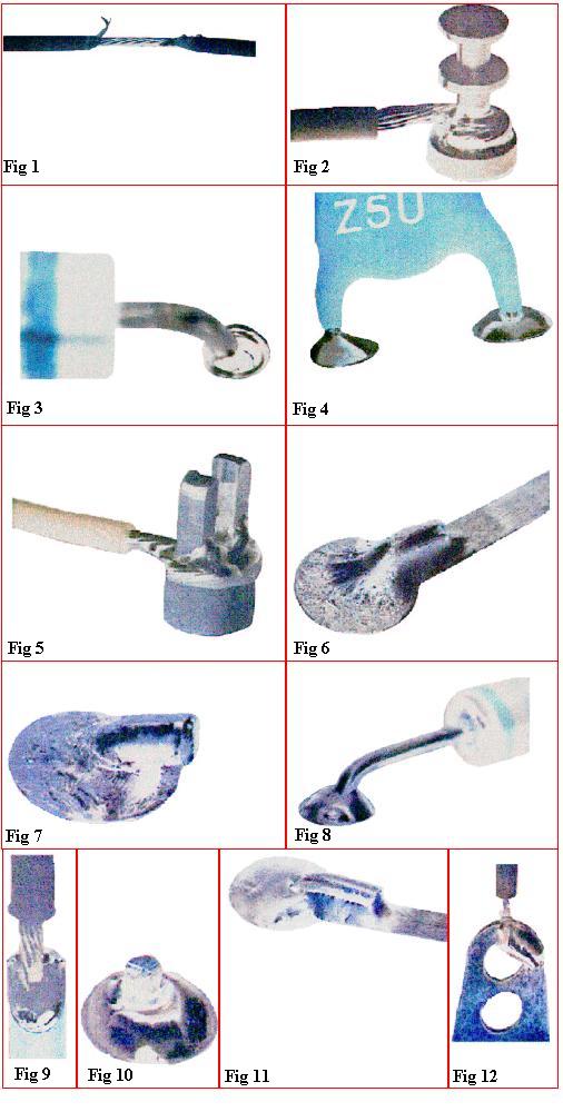
Fig 1 - Improper stripping of wire insulation.
Fig 2 - Birdcaged wire strands.
Fig 3 - Recessed solder.
Fig 4 - Part body (meniscus) in solder joint.
Fig 5 - Cold solder connection.
Fig 6 - Overheated solder connection.
Fig 7 - Fractured/disturbed solder connection.
Fig 8 - Poor wetting
Fig 9 - Blowhole.
Fig 10 - Rosin connection
Fig 11 - Dewetting
Fig 12 - Nonwetting.
Usually this problem is in the manual switch. The switch is wired in a different way than most manual switches. Enclosed is a schematic so you can see what I mean. Both NO and NC sides of the switch need to be healthy for the motor to work properly. The motor switch has a higher current rating than the other SPST switches used in the unit. If you swap be aware that the others are under rated for this application and will not be up to the task for very long.
I will post this reply on Film-tech also.
If this is not the cure please write.
Goodluck.
Don Olson
Component Engineering
As always it pays to ask the guys who know....
Ken, I agree this site is invaluable in getting information that others might be tempted to selfeshly hold back. I think the greater good is served, however, in that by helping each other with solutions to various problems, we help the world to make sure that "movies (especially on film) are still your best entertainment."
P.S. Will get back to this theatre in the next day or so, and will post my results. Thanks again to all of you.