This is topic Drive-In FM Transmitter: Identification, Manual, and Volume Problem in forum Film Handlers' Forum at Film-Tech Forum ARCHIVE.
To visit this topic, use this URL:
https://ft-forum.com/ft/cgi-bin/ubb/ultimatebb.cgi?ubb=get_topic;f=1;t=006469
Posted by Daryl C. W. O'Shea (Member # 1303) on 08-17-2004, 02:40 AM:
Does anyone recognize what make/model transmitter this is (white unit at top)? Apparently it has a 20 watt output. It transmits in (user selectable) mono or stereo. There are absolutely no labels, tags, or any other identification on it. It's most likely some kit, since it has no identification.
If anyone knows 'what' it is, would anyone have a manual for it?
Better yet, would anyone know how to boost the volume level it transmits? The source isn't the problem, if the source level is increased it clips in the transmitter (definitely not in the pre-amp feeding the transmitter). As it stands now, if you normally listen to the radio at about a third of your radio volume, you have to turn it all the way up to obtain the same level when listening to this transmitter. Not good.
Alternatively, it may not be a transmitter problem at all (I'd still appreciate knowing what it is and a manual though). The antenna is located at the opposite end of the building, probably 50', so maybe it's the cable run. I'd image that quite a few dB are going out the window there. I don't why it's located there, it used to be closer. The cable is in good shape though, and the meter on the transmitter, which as far as I'm told indicates how well the antenna is matched (the knob on the left has 10 positions which affect this meter level), is usually pegged at about zero -- just before the red zone.
I have no idea what is being used for an antenna. I can only hope that it's a proper antenna. It looks just like the antennas in use at some other drive-ins which have no problems.
Thanks! Now that I've typed this out, it probably is the long cable run. Comments still appreciated though!

Posted by Kenneth Wuepper (Member # 1174) on 08-17-2004, 07:43 AM:
Daryl,
Can you fill in a few blanks for us? What frequency does the unit transmit? I assume that it is Frequency Modulated and operates in the Broadcast band.
I am not up on Canadian Broadcast Law but 20 Watts would be very illegal in the US. The US transmitters for drive in use utilize the "shorted transmission line" type of antenna which is buried in the field and the signal is limited to the near area of the drive in. Is there enough signal in the drive in to quiet noise in the car receivers? That is what the antenna will effect.
The meter scale on the face of the transmitter appears to be the VU type. What does that meter read while sending audio to the transmitter? Does the audio signal input cause the meter to "hit the pin?"
There are a lot of broadcast engineers here on the Forum and perhaps we can help diagnose your problem.
KEN
Posted by Jack Ondracek (Member # 1466) on 08-17-2004, 08:28 AM:
Daryl:
The transmitter is from Panaxis Productions. PO Box 130 Paradise, CA 95967-0130 (916) 534-0417.
http://www.panaxis.com
I've got some of those boxes going back to '87, though I've since converted to Broadcast Warehouse transmitters.
It's what's inside that's the rub here. To start with, Panaxis transmitters don't go that high, power-wise, though they should have plenty of power for a drive-in... and a gain antenna would certainly fill-out the corners. And... Ken's right. If that thing is really running a drive-in at 20 watts, you want to be running in the opposite direction! I doubt 20 watt amplifier & power supply would fit in there with the other stuff though.
That box, and the components inside are sold separately, so the exact combination will be hard to nail down without a picture. If it's any more than a couple years old, it could have a stereo generator card (if they transmit that way), and maybe a compressor card, in addition to the power supply and transmitter assemblies. Everything is purchased separately, allowing you to mix-n-match to suit your needs. That particular combination of cards would fill the box. Overall performance is decent enough, though the power level is more like a bit over 250mW or so, depending on the match. It wants a 50 ohm load, though it's pretty forgiving of mismatches.
The VU meter is meaningless. It could be wired through that selector switch to monitor various parameters. However, I didn't use it, because the meter had no buffer and tended to load anything it was supposed to be monitoring.
Oh... everything in there is normally sold in kit form, with some assembly available at extra charge. That could be an issue... or not... depending on who put it together.
Whether your audio is feeding compressor, stereo gen or transmitter directly, it has 10k inputs... consumer grade unbalanced. If that 40 watt Optimus is driving it, you should have some serious padding in front of the transmitter. Unfortunately, too many drive-ins are notorious for using Radio Shack amplifiers as mixers... maybe feeding booth or concession monitors, and taking a tap from the output to drive the transmitter. If it's running mono, look for a pot on the transmitter. If stereo, be careful. The stereo gen has a couple of adjustments that you need a scope and a tone gen to set up properly. The composite output is also on a pot, however, and that will affect the "volume". In the ones I had, it was turned pretty much all the way up. If you can find it (it's closest to the feed line going to the transmitter card), you can check that pot easily enough.
If it has a compressor card, the audio outputs have pots on them, so there's another possibility for getting your modulation up.
If you still need some info on this thing, figure out what's inside it... better yet, take off the top & shoot a picture. I can scare up some docs on it, if it's got what I think it has in there.
Jack
[ 08-17-2004, 01:01 PM: Message edited by: Jack Ondracek ]
Posted by Gordon McLeod (Member # 33) on 08-17-2004, 09:15 AM:
If that General Noise sorry I mean General Sound preamp is the driver it has a 600 ohm output to directly feed Altec Amps in the old simplex cloned general sound mono sound systems of that era
Probably a good 600:10K tranformer would be a good idea
Also is the clipping from the FM actualy modulating past its frequency range or are you clipping the audio on the input stage
the Decade transmitters also tend to clip easily as well
Posted by David Buckley (Member # 2600) on 08-17-2004, 01:59 PM:
Assuming the transmitter is FM: The antenna system and indeed output power will have no effect on the perceived volume level as heard by a radio. So assuming then receiving radios are "fully quieting" (ie solid reception, no audio artifacts)there is no point in playing with antennas etc in trying to solve your problem.
The perceived volume is entirely down to how much deviation the carrier has. Since this thing is modular and custom built, you need to find out why you cant increase level without increasing distortion. Job for a 'scope and a signal generator.
Posted by Daryl C. W. O'Shea (Member # 1303) on 08-17-2004, 05:39 PM:
quote: Kenneth Wuepper
I assume that it is Frequency Modulated and operates in the Broadcast band.
Yes, it is an FM transmitter currently transmitting at 90.1. I suppose I should have put that in the body of the post and not just the subject. It's not using a shorted transmission line, it's using an antenna on a mast.
20 watts didn't make a lot of sense to me either, but that's what I was told over the phone. I expect it's probably 200 mW or 250 mW like Jack said.
It is a VU meter, but as Jack said, who knows what it's wired to. It doesn't move in relation to the audio input signal level, it just pegs itself in one spot that changes when you adjust the knob.
Thanks for identifying it Jack!
That RatShack mixer amp is feeding the trasmitter via a line level out, not a powered out. I have no idea what the film audio signal comes into that mixer on, it's been years since I've touched anything in that booth (luckily), and even then it was only to run for one night. It's probably using 10k composite inputs for a CD player or something.
The mixer is being fed by those General Noise pre-amps, probably without any transformers if it was all setup by who I think set it up.
I'll try to get over there tonight to take some pictures of its guts if I can get out of the factory long enough. Anyone want to help setup some robotics?
Gordon, the clipping I mentioned is not the transmitter over mod'ing, I was just trying to say that the GS pre-amp is set as high as it can go (about 5.5) without clipping at the input stage of the transmitter.
David, reception is good throughout the field as far as I know.
Thanks for the help everyone. I didn't want to touch it not knowing anything about it, or if there was anything I could do to make it better (the lack of ID on the unit left me wondering if it was just some piece of junk).
Posted by Gordon McLeod (Member # 33) on 08-17-2004, 06:45 PM:
My bet is that it is the GS preamp clipping due to an impedance mismatch loading it down
Put a scope on the input to the transmitter and run a tone loop and see if the audio going in is clipped as you raise the fader
Posted by Daryl C. W. O'Shea (Member # 1303) on 08-17-2004, 07:45 PM:
Will do as soon as I can get out there. I'm going to try to get out with my camera tonight to see what's inside the transmitter. I don't think I'll have time to go home for my scope though and pulling one out of a rack here wouldn't be too much fun.
Posted by Josh Jones (Member # 447) on 08-17-2004, 10:16 PM:
Open it up and trace the audio path up to the modulator.
Dont be so sure you couldnt cram 20 watts in there....its been done ![[Wink]](wink.gif) Solid state PA's these days are quite small. for that power level, you'd need about 30VDC to the final stage.
Solid state PA's these days are quite small. for that power level, you'd need about 30VDC to the final stage.
Josh
Posted by Jack Ondracek (Member # 1466) on 08-17-2004, 11:50 PM:
That's true, Josh.... by today's standards... but it's not the way the company packaged their products back when that box was common. The circuit assemblies were on fairly roomy cards... something like 4X4. I'll have to go find one of mine... I'm not completely sure it was even double sided. The power supplies are common full-wave bridges... no switchers... and no heat sinks or fans for an amplifier.
The transmitter's based on a PLL chip that's no longer available. I have a few of them left, but time has passed them by. Like I said though... it was a pretty decent circuit for its time. I'd much rather see one of those in a booth than some of the other cludges that drive-in operators have come up with for FM. After all... FM was supposed to be an improvement over car speakers. However, I've even seen analog FM bench oscillators in use as transmitters... with antenna amplifiers from Rat Shack to boost the signal... and they're still in use... really crappy sound, too.
Posted by Daryl C. W. O'Shea (Member # 1303) on 08-17-2004, 11:58 PM:
I slipped out for half an hour and went over to take some pictures. There are two 4"x4" boards in it, in addition to the power supply board. I'll upload them as soon as I get home, hopefully in the next couple of hours.
Posted by Daryl C. W. O'Shea (Member # 1303) on 08-18-2004, 03:42 AM:
Jack, I uploaded the full size photos to the server. DCP_2070.JPG and DCP_2072.JPG have the most detail.
http://www.film-tech.com/~dos/fmtransmitter/
Thanks Jack!
I take it this audio transformer would be suitable?
http://www.e-sonic.com/acc/products.aspx?partID=109N&partIDExt=195&command=detail
It looks like the film audio is being fed to the Rat Shack mixer/amp via the phono/CD composite input. I'd image it is set to CD. I didn't have time to pull it out during their intermission to look, I just barely had enough time to get the transmitter pictures while the intermission clock was running.
edit:
Egad! I just found the manual for the Optiums MPA-50. Now I remember why you shouldn't believe anything you're told by someone with a problem. The MPA-50 doesn't even have a line level out. Only 70V, 16, 8 and 4 ohm outs. I'm surprised they haven't blown the transmitter input stage away.
[ 08-18-2004, 05:12 AM: Message edited by: Daryl C. W. O'Shea ]
Posted by David Buckley (Member # 2600) on 08-18-2004, 07:17 AM:
Ye gads.
The mains inlet is very naughty. Actually, its downright dangerous.
It does look like the switch is a selector for the meter. The meter is indeed unbuffered as Jack suggested above. If the source impedence of whatever feeds this is really low then thats fine, but anything else it'll shunt like hell. Not to mention there appears to be a cap across the meter which will act as a hi-cut filter when an input is connected to the meter. Not good. Anyway, looks like both input channels are selectible, and something else, maybe supply voltage, and audio level to transmitter.
The latter looks like the white wire (insert bomb joke here) connected to the link between the two boards. I suspect that this is the audio path you should have a scope on. And I further suspect that the nearby blue preset is the modulation depth.
Theres too much stuff on the first board to just be a preamp or mono summation - the quad opamp in the corner would do all that. Just noticed - theres a crystal on the pre-amp board. Whats that all about? Cant see the numbers on the chips there. The only thought that wont go away is a BBD delay line, but why? (update: The board being a stereo encoder explains the purpose of this crystal)
The power output of the transmitter must be under a watt. The heatsinking is insufficient to support much power at all.
And whoever built this clearly wasn't aware of good practice of grounding in an audio system - theres ground points all over the place.
I'm confuzzled, so I'm going to bed now - I hope I dont have nightmares over this thing :-)
[ 08-18-2004, 02:46 PM: Message edited by: David Buckley ]
Posted by Paul Trimboli (Member # 1509) on 08-18-2004, 09:01 AM:
When you say there are earthing points all over the place, well they all earth back to the metal case? I always thought that is correct?
Posted by Gordon McLeod (Member # 33) on 08-18-2004, 09:40 AM:
The dip switchs set the frequency division from a master oscilator that the crystal controls
Posted by Jack Ondracek (Member # 1466) on 08-18-2004, 12:40 PM:
The board on the end is the stereo generator. You can adjust the modulation level by the blue pot closest to the corner.
The board with the two heat-sinked transistors is the transmitter. As Gordon says, frequency is controlled by the settings on the dip switch. By the voltage regulator, there's a place for a jumper that will raise the voltage to the "final". If the jumper isn't there, it only puts out around 100mW.
The stereo gen doesn't have a lot of headroom, so incoming levels are a concern. As the transmitter has no compressor/limiter, I'd imagine things can get interesting for the listeners if you get the clipping resolved.
As there's no indication of outside padding in there, how the ratshack amp feeds it sounds like an interesting place to start!
I've got manuals & schematics for all that stuff. If you can wait for me to get my scanner going, I'll email it. Otherwise, if you send me an address, I'll copy this stuff & mail it to you.
Jack
Posted by Gordon McLeod (Member # 33) on 08-18-2004, 01:33 PM:
I would appreciate a copy of them scanned as well thanks
Posted by Kenneth Wuepper (Member # 1174) on 08-18-2004, 02:20 PM:
Since this is a cinema related application, could you add those diagrams to the manuals section?
I would bet that someone turned up that power amp or even got a feedback which sent the audio input op-amp into rapture. The microphone is awfully close to the Boom Box field monitor.
KEN
Posted by David Buckley (Member # 2600) on 08-18-2004, 02:40 PM:
quote: Paul Trimboli
When you say there are earthing points all over the place, well they all earth back to the metal case? I always thought that is correct?
Nope, thats earthing done real bad.
There should be a single ground point for the whole assemblage, to which each earth wire returns. This is called star earthing. The principle is to stop currents circulating throught the earth system. Such circulating currents can lead to all kinds of problems, from hum superimposed on the signal, to instability.
Posted by Daryl C. W. O'Shea (Member # 1303) on 08-18-2004, 04:51 PM:
I agree, the grounding is all messed up.
Looking at the board it was clear the dips were the frequency selectors.
First thing to do is to do something about the Rat Shack amp.
Not too worried about feedback as that radio is used for non-sync music, but you never know.
Would appreciate the manual in any form convenient to you Jack. If you'd prefer I can scan them for you if that is easier.
Thanks again everyone.
Posted by Daryl C. W. O'Shea (Member # 1303) on 08-21-2004, 01:25 AM:
I received the manual and schematics for the transmitter (via FedEx International Priority, BTW -- thanks so much Jack!) today and was able to adjust the gains on the stereo board and on the FM exciter, both were fairly low.
I also added a transformer between the preamp (I love Electrosonic, ordered at 5:15pm, out the door at 6:30pm, had it at 10:00am) and the soon to be thrown out mixer amp, which helped a little. The big problem is the impedance mismatch between the mixer amp and the transmitter though.
I'm in the process of tracking down a good mixer that has a pair of XLR inputs, a 1/4 mic input, a composite RCA input for non-sync (or just another 1/4 input), and 600 ohm or 10k ohm stereo outputs.
I'd love to install a real cinema processor with noise reduction, but unless I can get one real cheap I don't think it's in the budget since they'll be spending $2100+ to upgrade their analog readers in their Century R3s-- which reader is yet to be decided on (it'll be either BACP or Kelmar).
For anyone who's interested, the transmitter as it's currently set up has a power output of 250mW. Moving a single resistor changes the power output to 500mW.
Posted by Josh Jones (Member # 447) on 08-22-2004, 04:06 PM:
I built a 5 watt VCO transmitter several years ago from scratch that didnt use heat sinks that big! Although considering the technology, at least you have PLL ![[Cool]](cool.gif)
Josh
Posted by Daryl C. W. O'Shea (Member # 1303) on 08-29-2004, 10:41 PM:
At least they won't have to worry about it overheating when the booth hits 40 degrees in the summer.
In case anyone is interested, here's the input/output specs for the mixer I bought, a Yamaha MG10/2. Which is a realy nice board for the $159 it cost me. I actually went in to order a Soundcraft Spirit Notepad, which is similar, with fewer channels, a plastic rather than metal case, and nearly twice the price.
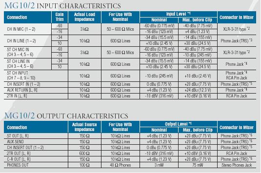
Hopefully I'll get some time to install it sometime this week.
Powered by Infopop Corporation
UBB.classicTM
6.3.1.2