This is topic Interesting 3 Phase Motor Problem, Or How To Save Six Hundred Bucks in forum Film Handlers' Forum at Film-Tech Forum ARCHIVE.
To visit this topic, use this URL:
https://ft-forum.com/ft/cgi-bin/ubb/ultimatebb.cgi?ubb=get_topic;f=1;t=006644
Posted by Mark Gulbrandsen (Member # 72) on 10-17-2004, 01:09 PM:
The motor on a Phillips FP-56 projector I recently aquired was supposed to be a 220/380 volt motor but as it turns out 380 volts must be a common voltage in Scandanavia and Europe as the motor was wound for 380 volts ONLY in spite of the 220/380 volts stated on the motors spec plate.
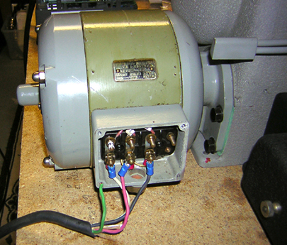
Now this is a special direct drive motor made just for the post war FP series projectors and it would probably have to be rewound for 220 volt at a cost of close to 600 dollars, motor shops didn't think the windings could be reconfigured for 220 volt without it being rewound.
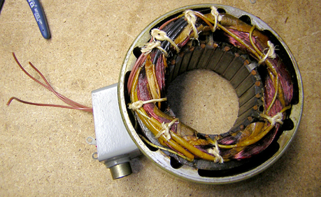
Fortunately, I also had another of these motors which came from South America on loan from a friend that was wound for both voltages and after comparing both stators they had exactly the same number of coils and slots in the stator so ultimately they had to have the same exact windings in there.... they also both had the same measured resistance when the loaner was set to 380 volts.
With a 600 dollar re-wind job looming and nothing to loose on this motor I decided to cut the ties and tape from the end of the stator where all the connections from the coils were made.
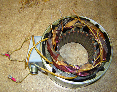
Low and behold I found the other end of the windings commoned together and I decided to cut those and measure the resistance. As it turns out these were the other three connections that were not brought out to the 6 connection terminal block for what ever reason... to save a few cents at the factory or perhaps this motor had been re-wound at some point in its life.... it looked alot dofferent than the other stators windings. Anyway I brought these three out to the terminal block and got the sets of windings in phase and again measured resistance and found it to be the same as the loaner motor when it was set to 220 volts. After re-tying and revarnishing that end the end of the motor its running just fine off of a 120 to 220 three phase motor invertor and I saved six hundred bucks.
I also learned from all this that motor repair shops in this area are pretty much a joke and there are few if any that are willing to even take the time to even see what one has before they quote a job.
Posted by Paul Mayer (Member # 355) on 10-17-2004, 04:49 PM:
Mark, very cool! ![[thumbsup]](graemlins/thumbsup.gif)
Posted by Gordon Bachlund (Member # 124) on 10-18-2004, 01:27 PM:
Mark, 220/380V 3-phase 4-wire is common in Europe, just as 120/208V and 277/480V 3-phase 4-wire is common in the US.
I applaud your resourcefulness!
Posted by Phil Hill (Member # 371) on 10-18-2004, 07:01 PM:
So Mark, NOT to be an asshole and take away from your great solution, BUT!, I feel I ***MUST*** comment on a couple of things that caught my eye in your pics.
1) It is customary, even in "test" set-ups, NOT to use the "white" lead as a phase.... mostly wrap blue tape (or?) around the lead to designate it is a phase and not a neutral.
2) BUT! More significant is that un-grounded/terminated GREEN safety ground to the chassis/projector! JFC! Mark! After all these years of knowing you, I am totally surprised! Please include me in your will... ![[Wink]](wink.gif)
OBTW: Great going on the solution of the motor voltages! ![[beer]](graemlins/beer.gif)
(Just couldn't resist yanking yer chain, my friend!) ![[evil]](graemlins/evil.gif)
>>> Phil
Posted by Mark Gulbrandsen (Member # 72) on 10-18-2004, 07:20 PM:
Thanks Guys!
Phil, Its actually a very good idea to point out anything in any picture of situation that you see is wrong!!
In this case it was just a quick test setup on my bench at home and I used what ever piece of 14/4 SO that I had laying around. The green wire is stuck in the hole for one of the cover screws and you are indeed correct about it needing a permanent ground... and correct oolor wires... especially with a variable frequency drive. Oddly enough this motor ALSO had a short from one of the windings to the case(which is very likely why the projector was retired from service) and the first time I had the ground attached the drive unit didn't like it and shut down. The motor ran fine with the ground lifted but there was 220 volts between the frame and that ground wire.!! I had the ground disconnected, or not permanently attached so I could measure between the frame and the actual ground lead for leakage... Once the short was taken care of, which fortunately was not serious, and no leakage reading was found then the wire was temporarily stuck in the hole to afford some ground. Don't worry... I won't electrocute myself... there is also a rubber mat on the floor where I sit. I also work on vintage TV's at this bench!
Whats more important is whats on the other side of the motor..... A very little used almost like new FP-56.

Mark
Posted by Daryl C. W. O'Shea (Member # 1303) on 10-18-2004, 07:22 PM:
How spoiled I must be with a 220/380V 3 phase panel. ![[Big Grin]](biggrin.gif)
Oh wait, (some of) the damn European machines that break like clockwork make it not worth it.
Posted by Steve Kraus (Member # 476) on 10-19-2004, 07:08 AM:
Mark, what sort of resistance readings did you get? Since a motor winding to the tiny direct current from a meter is just a length of wire I would imagine the resistance would be extremely small.
Posted by Mark Gulbrandsen (Member # 72) on 10-19-2004, 08:20 PM:
The reading on both my motor and the loaner motor was about 20 ohms measured between phases with the motor straps set for 220 volts. Set at 380 it was close to 40 ohms between phases. Set at 220 the windings are delta configured with sets of windings in series-parallel(2 sets of windings in series and those stacks of two are paralleled) and set at 380 its wye configured with sindings in series. There are 12 seperate windings in this motor which has 24 slots in the stator... Its easy to figure from there because its a 4 pole motor(sync by the way) and there are multiple windings in series per phase. One single winding would measure very low but in series/parallel for 220 volts they come out to 20 ohms.
The motor actually draws way less than its rated current of 1.2 amps load at 220. Running this FP-56, the actual draw per leg is about .6 to .8 amps. It drops a bit to .6 when the mechanism has been running for a while which is a normal thing... both motors do pretty much the same thing. Neither motor gets very warm even after running well over 2 hours.
Mark
Posted by Steve Guttag (Member # 268) on 10-20-2004, 12:13 AM:
If an impedance bridge is handy...setting it to 60Hz can often reveal what is going on in a motor's windings (or transfomer) better than mere DC resistance.
Steve
Posted by Mark Gulbrandsen (Member # 72) on 10-20-2004, 07:05 PM:
I would LOVE to have a nice impedance bridge but have yet to find one that I would want to own. I perfer the much older bridges that have the really good Weston meters on them. If anyone knows of one let me know!!!
One thing though, this was a 50 hz motor which I failed to mention in the above posts.
Mark
Powered by Infopop Corporation
UBB.classicTM
6.3.1.2