This is topic Best sound test film for clipping in forum Film Handlers' Forum at Film-Tech Forum ARCHIVE.


To visit this topic, use this URL:
https://ft-forum.com/ft/cgi-bin/ubb/ultimatebb.cgi?ubb=get_topic;f=1;t=007181

Posted by Matthew Taylor (Member # 2310) on 05-11-2005, 10:14 AM:
 
What is the best type of sound test film to test for clipping on an oscilloscope, ie with the greatest modulation?
 
Posted by John Walsh (Member # 168) on 05-11-2005, 11:25 AM:
 
I would think; none. To get an amp to clip (for testing purposes) you need to input a signal that is higher than the amp is supposed to take. This means using a signal generator where you can increase the input signal and watch the resulting output on a scope. The amp manufacturer should be able to provide enough data to insure your sound system is set up correctly and won't clip.

If I had to do this with test film (which I don't recommend) I guess I would use a loop of SMPTE 1kHz test film, then turn the volume up until I saw clipping on the scope. Most manufacturers' test (and their data is based on) using a 1kHz tone. I would not use regular film (with music and dialog) since the sound is too random and brief to see and record.

If you can tell us why you want to do this, we might be able to tell you a better way to get the result you need.
 
Posted by Matthew Taylor (Member # 2310) on 05-11-2005, 11:42 AM:
 
Sorry, I should have been more clear. I want to make sure that the solar cell the right distance from the film so no clipping of the signal occurs. I have already set up the lateral position of the cell so crosstalk is about 8:1 signal/noise ratio but I appear to be getting a bit of distortion on high output soundtracks. I wanted to see if it's the cell position or a bad preamp setup.
 
Posted by Rick Long Jr (Member # 541) on 05-11-2005, 12:19 PM:
 
I think Dolby's Cat. 97 is 100% modulation, and is the film used to check the cell position, both laterally, and for proximity to the film. (the less crosstalk, the closer you are)
 
Posted by Pete Naples (Member # 761) on 05-11-2005, 05:13 PM:
 
Yup, Cat97 L-R is about all you can get these days, and it is recorded at 100% mod, look for the tops of the on peaks going flat. It is amazingly easy to overdrive a cell!
 
Posted by Matthew Taylor (Member # 2310) on 05-11-2005, 05:22 PM:
 
Ok..well, I've already set up using cat 97 and got minimal crosstalk and zero clipping so I guess the problem is with my preamp setup.
 
Posted by Pete Naples (Member # 761) on 05-11-2005, 06:48 PM:
 
what's the pre-amp?
 
Posted by Sam D. Chavez (Member # 1841) on 05-11-2005, 08:55 PM:
 
Cat. No. 97 is actually slightly clipped on the outside edges as it is.

I'm not sure I understand the term clipping the solar cell.

Do you mean like overdriving it with too much light, or do you mean the waveform from the film is too big to fit inside the dimmensions?
 
Posted by Matthew Taylor (Member # 2310) on 05-12-2005, 03:47 AM:
 
Sam, I mean that the cell is perhaps too far forward so the more modulated parts of the track are projected wide of the cell.

Peter, I use a cheap B-Tech stereo Mic amp. I have de-coupling capacitors on each channel of the cell and a couple of 680ohm resistors connected from the each channel to the ground.
 
Posted by Gilbert Travin (Member # 2138) on 05-12-2005, 04:53 AM:
 
Hi !

the stereo cell must be set very close to the film (1 mm is a good value, you can see CP-50 manual on this site : there is a scheme).
For coupling to preamp : it is better to avoid capacitors (capacitors are no reliable components !!! [Big Grin] ) but it is depending on your preamp .... The ideal solution is to use transformers as CP-50 do !
 
Posted by Gordon McLeod (Member # 33) on 05-12-2005, 06:09 AM:
 
be aware that there is a DC component in the output of the solarcel and some small cheap transformers do not like the DC component as it can saturate them
Best is a blocking capacitor in serries with the transformer
better yet get a used cp50 or similar
 
Posted by Matthew Taylor (Member # 2310) on 05-14-2005, 02:16 PM:
 
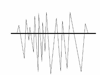
I have been trying to diagnose the distortion I am getting on louder parts of the soundtrack. I hooked up my scope to the preamp output and there's definitely no clipping going on. I ran some trailers and watched the scope output. I noticed that on the louder parts of the soundtrack the wave seems to extend further in the negative direction than it does in the top direction. I have tried to represent this in a dodgy diagram;

 -

Is this the reason my sound is distorted with loud bits? If so, what can I do about it?

BTW, if I run the 7khz test film, the wave is equidistant around the centre line.
 
Posted by John Walsh (Member # 168) on 05-14-2005, 04:13 PM:
 
Having the 7KHz waveform look symmetrical, but not the waveform from a soundtrack, seems almost impossible. A wild guess would be something weird like one half of a class 'b' preamp is bad. Where exactly do you have the scope probe connected? Is the scope input set to DC? Is this visable in both (Lt-Rt) channels?

As Gordon noted, a capacitor will remove the DC, and I would think there would be a cap at the input of the power amp. So even if it's not of equal ampiltude at the preamp output, it will be inside the main amp.
 
Posted by Matthew Taylor (Member # 2310) on 05-14-2005, 04:26 PM:
 
The scope was set to AC and measured at the output of the preamp. The preamp is really basic and built around a dual op-amp (4558). There are no transistors - only a few resistors and capacitors.
 
Posted by John Walsh (Member # 168) on 05-14-2005, 04:55 PM:
 
As far as I can tell, with the scope set to AC, the resulting waveform would have be symmetrical even if the signal is not. Only by moving the scope's up/down positioning knob could it be made to look offset. It might be interesting to set the scope to DC and see what you get.
 
Posted by Louis Bornwasser (Member # 3063) on 05-14-2005, 08:02 PM:
 
I think the requirement for a fully modulated film has lead us into thinking of overloads (electrical problems.) Based on the drawings of that scope trace, I think it more likely that there is an alignment problem causing one track to not be fully scanned. That would be the most likely reason for symetrical modulation on lower level material and non-symetrical modulation on 90-100% modulated material......just like AM radio does on purpose!!

Remember buzz track alignment is only one phase of scanning the track; the light source & the pickup must also be matched. Louis
 
Posted by Sam D. Chavez (Member # 1841) on 05-14-2005, 11:15 PM:
 
The waveform you show would look like this if the illumination is uneven and falling off at the edges as front scan systems do.

The Cat. 97 is the best test film to use as it is a pure tone and 100% modulation. Thus, you can infer from this what the peaks of real soundtracks will look and sound like.

The 7 kHz is only 70% modulation at best.

If you put your dual trace scope into XY mode you will see a vertical and horizontal vector representing the Lt and Rt channels. These should be the same length with no bends in the line. Depending on whether your system is front or reverse scan, you can move the light source and film until you get best illumination.
 
Posted by Manny Knowles (Member # 1171) on 05-15-2005, 11:30 PM:
 
If you want to verify illumination uniformity, the Cat. 566 test film was designed specifically for this purpose.

Sam's technique is useful for maximizing light output to the scanned area of the soundtrack.

I suspect that Cat. 97 is probably 97% modulation. Wouldn't 100% modulation create an optical clash situation? Or is clash what accounts for the crosstalk that is invariably encountered with Cat. 97?

[ 05-16-2005, 10:21 AM: Message edited by: Manny Knowles ]
 
Posted by Sam D. Chavez (Member # 1841) on 05-16-2005, 11:32 PM:
 
Manny,

The film is perfect, the crosstalk on front scan systems is caused by light scatter in the front scan projected slit systems

100% modulation is hard to characterize exactly as various companies have pushed the soundtrack envelope past the SMPTE legal boundries (.076) to get more dynamic range. Buzz track is at .084. Our readers are set to .082 as 100% modulation in recognition that the industry is both overmodulating the track past .76 and "cheating the septum" by making it smaller.
 
Posted by Manny Knowles (Member # 1171) on 05-17-2005, 02:07 AM:
 
I'm so glad I asked. Thanks, Sam.

So, is there danger of clipping and greater crosstalk if one of these overmodulated/underseptumized (?) tracks is played using heads that were designed strictly based on the requirements of the standards?
 
Posted by Sam D. Chavez (Member # 1841) on 05-17-2005, 11:38 AM:
 
Manny,

You are halfway there.

Clipping will take place "earlier" but crosstalk will be the same.

On reverse scan readers, it's a matter of the magnification of the soundtrack image onto the solar cell. The idea is to get the whole image of a 100% modulated soundtrack and have the DTS soundtrack and sprocket holes off the edges of the solar cell, sort of like having the undesired part of the picture image spill onto the black masking.

Each manufacturer sets the exact magnification based on their judgement on how much tolerance to allow for misprinting.

BACP does it somewhat optimistically which means the entire image gets played more accurately, but closer to the edge as it were.

So what is it you do In LA as opposed to Bermuda, or wherever you were last?
 
Posted by Edward Jurich (Member # 1787) on 05-17-2005, 09:34 PM:
 
It is not unusual for audio to have higher peaks on one side of the waveform. If you are getting distortion on high volume levels then you might want to check amplifier level settings to be sure you are not over-driving something.
 
Posted by Manny Knowles (Member # 1171) on 05-17-2005, 11:30 PM:
 
Thanks for all of this info. Now I've got to track down the relevant SMPTE standards.

quote: Sam D. Chavez
So what is it you do In LA as opposed to Bermuda, or wherever you were last?
Sam, I'm having a blast!

I just completed my BA in Cinema-Television at USC. I'm staying on thru the fall semester because there is one more of Tom Holman's classes that I would like to take. Ironically, it's his "Intro to Film Sound" class, but it has a number of practical demo's that he thinks I will enjoy. So, I'm going to do that and a research project involving independently-owned theatres.

I have also been working a number of part-time jobs at the university in the projection dept. (showing films for classes) as well as in the production sound dept. as an equipment manager, scoring engineer and re-recording mixer for some of the student projects. In this upcoming (and final) semester I will also be the teaching assistant for the scoring engineering class.

I'll be going back down to The Bahamas for a brief working vacation in about a week.
 
Posted by Matthew Taylor (Member # 2310) on 05-18-2005, 03:21 AM:
 
Sam,

When I put the scope in X-Y mode and put the probe on the preamp output, all I see is a single horizontal line. I don't know whether this is a problem with my scope or whether I'm doing something wrong.

I assume that if I balance the outputs of left and right by adjusting the light source while using the 7kz film that will at least stop some of the underscan. If there is still distortion then the light source probably needs to be moved back from the film to make the slit wider - right?

I am only referring to the 7Kz film because I have given back the crosstalk film that I borrowed so I don't have access to that anymore.
 
Posted by Sam D. Chavez (Member # 1841) on 05-18-2005, 10:23 AM:
 
Matthew,

You need two probes, one on the left channel and on the right channel to get true X/Y. If you have a mono system it wont give but one signal of course and you will only have one line.

The length of the line will be an indication of light output. With an LED reader, swivel the LED bracket up and down for strongest signal.
 
Posted by Matthew Taylor (Member # 2310) on 05-18-2005, 03:56 PM:
 
I had a look at the width light slit on the 7khz film and it seems that the slit is not wide enough to completely cover the soundtracks. Is it normally possible to adjust the lens to make the slit wider? Would this be the cause of the distortion?
 
Posted by Pete Naples (Member # 761) on 05-18-2005, 04:26 PM:
 
Some slit lenses are adjustable, earlier Cinemecannica and Fedi spring to mind. The procedure I use is to set everything up centrally using Buzz Track and Cat 97 Left-Right. Open up the slit width until it's over scanning on both sides, then narrow it until the buzz track just stop singing at you.

Underscanning could well cause distortion on busy parts of the track, to all intents and purposes the signal is being optically clipped.
 
Posted by Matthew Taylor (Member # 2310) on 05-18-2005, 04:43 PM:
 
The funny thing is, I cannot see any clipping on the scope. The peaks are nice and round.

My projector is a Prevost which I believe have very similar sound pickups to cinemacannica.

I am starting to think I have a dodgy solar cell which is not helping me with my alignment problems. It seems that one of the cell's outputs is greater than the other. I set up the cell with cat 97 and then adjusted the lens alignment until the scope showed equal amplitude on both channels. But the light slit looks way over to one side when projected on the cell, even though the output is equal. Also, without any film threaded, the dc output of the cell is different on each channel even if the slit is adjusted so it's equally covering both sides of the cell.

Where can I get a solar cell for a Prevost P70 and how much can I expect to pay?
 
Posted by Pete Naples (Member # 761) on 05-18-2005, 05:11 PM:
 
quote: Matthew Taylor
The peaks are nice and round
The peaks of Cat 97 shown on the scope shouldn't be round they should be fairly sharp, look at the illustrations in the early Dolby manuals (CP50) for guidance. IIRC those are actual oscillographs, not drawings.

Back to your predicament.

It's possible that the lens is full of oil and dirt, but I'm a little concerned by your use of Cat 97 to adjust the lens position. You should use buzz track to adjust the laterl relationship between the lens and the film path, then use Cat 97 to adjust the cell relative to the film path. The two adjustments do tend to play off against each other, so you check and adjust each one until you can make no further improvement. Then you set the scanning width accurately.

It's not unconceivable that the cell is damaged, they are fragile and do actually wear in use, especially if static is prevalent.If you really need I'm pretty sure we can supply a
cell and block for a Prevost, but I've no idea at what cost.
 
Posted by Sam D. Chavez (Member # 1841) on 05-18-2005, 07:50 PM:
 
I am not certain whether the Prevost lens slit width is adjustable, but it could account for the problem you are having.

The only problem I have wth Pete's procedure is that the Cinemeccanica's lens "iris" closes down unevenly giving you the impression that the lens is over the center of the soundtrack when its not. The best way I have found to get optimum adjustment of the the front scan Cinemeccanica readers is to splice a loop of half Buzz and half 97. This way you can keep working back and forth until slt width and cell postition are both optimized.

I do make a reader for the Prevost P55, P60, P70, P 90 as long as you have your original Prevost film guard and solar cell holder. I also make a reader for older P93's as well.

Commercial message aside, the cell should be pushed as close behind the film as practical.
 
Posted by Pete Naples (Member # 761) on 05-19-2005, 04:15 PM:
 
Sam, that's pretty much what I do, although I don't splice together a loop of buzz and Cat97, I run buzz, then left-right, then buzz, then left right, then buzz....., until no further improvements can be made.

If you want to see a slit lens that adjusts width un evenly, try a Projecson laser unit! It adjusts from one side only, which actually isn't that much of a problem. One adjusts lateral scan to get quiet one one side, then adjust the width until the other side shuts up.
 
Posted by Sam D. Chavez (Member # 1841) on 05-19-2005, 09:39 PM:
 
Pete,

All my method does is speed the process up as you will eventually break the film rethreading it or run out of patience and choke down the iris wen you get close enough.

I do the entire procedure in X/Y as you can clearly see buzz track modulation as well as the Cat. No. 97 vectors.
 
Posted by Marin Zorica (Member # 1716) on 12-18-2005, 01:53 PM:
 
It would be nice that somebody upload good pictures how oscilloscope and spectrum traces looks like when a chain is aligned, because manuals pictures are drowning, so if somebody got real picture from scope and spectral analyzer for A and for B chain as well!
 
Posted by Marin Zorica (Member # 1716) on 12-20-2005, 05:22 PM:
 
I got another question.

Should i with cat 69T (Dolby tone) set gain of preamplifier/processor to 0dB reading?

Because i got here equipment what don't have calibration, manual or any kind of documentation, but have VU meter from -25 to 6dB.

So is it Cat 69T 0dB level in movies or Cat 97 (100% modulation)??
 
Posted by Louis Bornwasser (Member # 3063) on 12-20-2005, 07:49 PM:
 
My understanding is that Dolby reference level is 50%modulation. Louis
 
Posted by Gordon McLeod (Member # 33) on 12-20-2005, 08:01 PM:
 
i guess i will post the question

quote "I got another question.

Should i with cat 69T (Dolby tone) set gain of preamplifier/processor to 0dB reading?"

the cat 69 is the 50% level as such typically 300mv

"Because i got here equipment what don't have calibration, manual or any kind of documentation, but have VU meter from -25 to 6dB."
the manual for all the olby products is on this site what more documentation does one need

So is it Cat 69T 0dB level in movies or Cat 97 (100% modulation)??

RTFM [Smile]
 
Posted by John Hawkinson (Member # 1135) on 12-20-2005, 10:08 PM:
 
I think Marin has a non-Dolby processor.

--jhawk
 
Posted by Marin Zorica (Member # 1716) on 12-21-2005, 02:48 PM:
 
Yes it's non-dobly processor!

What's RTFM??
 
Posted by John Hawkinson (Member # 1135) on 12-21-2005, 02:57 PM:
 
RTFM is a crude way of telling you to "read the instructions."

It would help if you could tell us more about the processor. What model and brand?

The discussion in the other thread about setting levels with Cat69T is about setting the preamplifier levels for proper Dolby A and Dolby SR decoding (300mV). But you seem to be talking about the main output level when you discuss a VU meter from -25dB to 6dB.

This makes it quite confusing. We do not understand your question.

The preamplifier gain needs to be set properly so that Dolby decoding can take place, and that voltage is internal to the processor. If you do not have Dolby decoding, then the preamplifier gain is less critical. Others may have better advice, but I think you probably want to set it to the middle of the range between the minimum sufficient to hear the track and the point at which clipping is noticable.

As for the master output gain of the processor:

When you calibrate the processor, you should set it to a nominal level (probably does not matter much what exactly it is) and inject pink noise into the processor, and adjust for 85dBC from the speakers. Do this once for each channel.

When you play a film, start at the nominal volume level to which the process has been calibrated, and adjust "by ear."

If your question is what nominal level to choose, in your case I would use 0dB, but it is arbitrary (as long as you have sufficient headroom to make soft movies louder and loud movies softer).

--jhawk
 
Posted by Brad Miller (Member # 2) on 12-21-2005, 03:45 PM:
 
John, you have never installed a Dolby processor, have you?

First, he has a CP50.

On the CP50 is a card (cat109) with analog meters on them that are used to quickly calibrate dolby level with a dolby tone loop running (make sure you are in MONO when you do that Matthew.) That is what he is referring to.

Remember also he has cat64 cards, not cat64B cards. The levels must be set properly on those or even if everything else in the processor is spot on, he can have distortion.

Also it is important to calibrate the processor with the fader at 7, as it is "stepped" and calibrating at say "4" would end up with slightly skewed balancing between channels (levelwise) and also because 7 is the point in the fader where the lowest noise floor resides. This is why I always laugh when I walk into a theater and find the faders between 4-5. Properly calibrated, the fader should sit at 7 for most features and never go lower than 6, and yes this is without customer complaints. Any machine that has to run lower than 6 either has crappy speakers, poor aiming or was over-EQ'd by a tech looking for that perfect X curve (which causes the end result to sound like ass).

Marin - upload a picture of what the image looks like on your oscilloscope and we can tell you what's wrong. Just seeing a bench perfect alignment image won't help you figure out WHY yours doesn't look like the manual.
 
Posted by John Hawkinson (Member # 1135) on 12-21-2005, 04:15 PM:
 
Yes, Brad, of course I have. Though never a non-Dolby processor, which Marin said he had. Perhaps we're confusing Marin and Matthew.

The CP50 doesn't have a built-in fader, though, and any external fader is probably not marked from 0-10.

--jhawk
 
Posted by System Notices (Member # 2357) on 06-08-2009, 05:38 AM:
 

It has been 1264 days since the last post.


Powered by Infopop Corporation
UBB.classicTM 6.3.1.2