This is topic Christie AW3 Take-up Issue in forum Film Handlers' Forum at Film-Tech Forum ARCHIVE.
To visit this topic, use this URL:
https://ft-forum.com/ft/cgi-bin/ubb/ultimatebb.cgi?ubb=get_topic;f=1;t=007622
Posted by Thomas Dieter (Member # 2507) on 11-19-2005, 02:29 PM:
Recently I have been having a problem with 2 of our platters, and they are both happening on the bottem deck. The take-up is not able to keep up with the feed out of the projector, and so the show drops. All the decks are timed exactly the same, for all of our platter systems,and by the same person. We are not having any other problems except with these two. Here's the symptoms and solutions that our tech has gone through.
Problems
- Platter won't keep up with projector feed out.
- Only happens at the beginning of the show, usually end after first or second rolling stock ad.
- The motor has a harsh grounding noise.
Solutions Attempted - Tried moving motor to see if problem would follow. Failed
- Tried making sure the sodor for the LED and the solar cell were good. Failed
- Made sure drive wheels were still good. Looks Good
- Made sure the Drive wheel rim was clean. Looks Good
- Tried changing out LED/Solar Cell Assembley. Failed
- Tried retiming the decks. Failed
If there are any other possible solutions that have yet to be tried, this would be helpful. Thanks in advance.
Posted by Monte L Fullmer (Member # 2797) on 11-19-2005, 02:52 PM:
Hi Thomas - did you swap out the sensor assembly? They may look good, but they can get tired and start to short out. This happens many-a-times with these sensors, especially where you have the older AW3 unit.
Is the notch in the filter wheel aligned to the edge of the PE cell with the mark on the "0" degree position? - as mentioned in the manual?
Motor grind-brushes are tired or even bad. Take the brush caps off and inspect the brushes (which they shouldn't be bad since the motor's RPM is so low), or could be the bearings. Do a motor swapout in such case.
Timing factor - even though the book mentions (do you have a "platter tachometer") a certain RPM setting for the HIGH and LOW pots in the tower, you have to make your own settings at times for unit to operate correctly. Do you know how to properly time a AW3 with a VOM meter and the proper procedures that is listed in the manual?
little tips to help you out. thx-Monte
Posted by Dominic Espinosa (Member # 2122) on 11-19-2005, 02:52 PM:
What kind of grinding noise?
They sound something aweful when they're not receiving enough current to run, but creep.
Try swapping the make switch card or the LED card (the one with the 3 pots on it).
There's not much else it could be if the motors run fine elsewhere.
EDIT: Monte, you beat me to it!
Check what Monte said, however, the Hi/Lo pots shouldn't be at fault if it's dying on takeup.
However, on the subject of timing sometimes you have to trim the resistance way down, i.e. instead of 25k some of our platters run perfectly at like... 12.6k or so.
Why this is I'm not sure but that could be a factor as well.
Posted by Monte L Fullmer (Member # 2797) on 11-19-2005, 03:11 PM:
12.6K ohm on the LED resistance? (OUCH!) Should be down to 70 (-/+ 2) ohms with the pointer on the 70 degree mark..and use a digital VOM meter.
-Monte
Posted by Brad Miller (Member # 2) on 11-19-2005, 03:11 PM:
Sounds like the led below the axle to me. Swap that with the middle deck and see if the problem doesn't follow.
Posted by Dominic Espinosa (Member # 2122) on 11-19-2005, 04:50 PM:
quote: Monte L Fullmer
12.6K ohm on the LED resistance? (OUCH!) Should be down to 70 (-/+ 2) ohms with the pointer on the 70 degree mark..and use a digital VOM meter.
Word, it seemed weird to me too. Some of them run that way though. I really can't explain it.
Anyhow, to clarify, Monte's suggested timing practice is ala the Christie manual.
The process I was referencing was the FT AW3 tweaking guide.
Feed arm at full, resistance should be 25k.
With the exception of a few oddball systems.
Posted by Monte L Fullmer (Member # 2797) on 11-20-2005, 01:18 AM:
Oh, okey after reading this section in the "tips" area, I can see where you're coming from.
Yes, the Ohms will be that high with the shutter disc fully in the open position.
But, the shutter usually isn't in this position during normal payout and rewind operation is why of the manual's recommended timing factors for a smooth and steady payout and rewind.
There can be more room for error using this alternative method since the recommended factors can point out more areas of concern in a more precise method and corrective measures can be used in such areas needed for a smooth operation.
This all comes from my years of working on vehicles with ignition timings using feeler gauges for point gap settings, strobe lights and dwell meters. Plus, in doing belt changeouts for overhead cam vehicles (and belt changeout on projectors): there is no shortcut in making things run smoothly.
One must follow proper procedures for the vehile to perform most effective and efficently. And doing platter timings of any platter make is exactly the same as I have mentioned above.
But, I guess if this alternative method works for some, then so be it.
Not for me to say what is right or wrong.
thx-Monte
Posted by Thomas Dieter (Member # 2507) on 01-08-2006, 11:12 AM:
Okay, our tech and myself have tried just about everything to see if we can get this problem fixed. We got the problem fixed on one, but the other is just not cooperating. We have changed out the Solar Cell Assembly, We have Swapped out the Solar Cell Assembly, we have swapped out cards, we've tried new cards, we swapped out motors. The problem doesn't follow to another deck or system, rather just stays there. The tech says that we've just about everything cept gutting the system of it's wires and rewiring it. I really don't want to do that.
What's really confusing is that you would think that the fix for one of our platters would be the fix for the other as they are having the same problem and same symptoms. The other platter that is now working just needed to have the solar cell replaced, and no problems have occured. What else could be wrong? I'm going to be gone to Marietta, GA to help at our location there. I plan on getting pic and sending them, but when I get back, I want to see if any of the solutions that you guys post might work.
Like I've said, we've swapped motors, swapped cards, tried new cards, swapped solar cell assemblies, tried new solar cell assemblies. The problem doesn't follow or go away. What to do?
BTW: The grinding noise that I was talking about happened to be the Drive Wheel. It had gotten to the point that it was starting to stick to the hub of the deck and that's what that noise was. We put on new drive wheels, and the grinding went away.
Posted by Michael Schaffer (Member # 1204) on 01-08-2006, 11:24 AM:
Maybe the platter hub or the three washers it sits on are worn or just too dirty. Did you check if you have the right washers? The think one on the bottom, then the bearing washer and finally the thick washer on top. It might help to clean all the parts thoroughly and regrease them.
Another thing which often happens with Chrirtie platters is that the pin inside the axle which keeps the brain from spinning gets loose and starts wandering outside, biting in the bushing on the inside of the hub.
Posted by Louis Bornwasser (Member # 3063) on 01-08-2006, 02:45 PM:
Sounds like you have changed literally everything. The one thing not mentioned is the wires going to the motor. Remember they loop up through the makeup pushbutton switch. Try exchanging one of these plug in switches for another on another platter. Louis
Posted by Steve Guttag (Member # 268) on 01-08-2006, 03:47 PM:
Okay...hang on a second there.
Put a payout head in the platter with the problem...
Take the take up arm and move it briskly but not in a jerking fashion back and forth...look at the feed fingers on the payout...they should be swinging and tracking precisely with the take up arm (note they will be swinging in the opposite direction as they do on payout).
If they done move smoothly and track precisely with the take up arm you have several potential problems.
The bearings in the platter spindle (not the big flat ones, the ones that allow the variable density disc to spin) may be binding. If it is binding at all...you will need to pull the spindle assy and clean (and possibly replace) the bearings and set the return spring tension.
The take up "pawl" may be bent/broken. Take the take up arm assy off from the arm (just for 1/4-20 screws) and inspect this white nylon finger. It should be free from damage (and be completely there). If need be, look at one of the platters that works to see what it should look like). Now, move the take up arm while holding onto its mounting plate. The nylon finger (pawl) should be spring loaded and it too should be moving freely and forcably back to its rest position.
Steve
Posted by Mark Gulbrandsen (Member # 72) on 01-08-2006, 07:12 PM:
I agree with Louis on this one ![[Cool]](cool.gif) check the make up switch assy. I replace about a half dozen of these a year for various reasons.
check the make up switch assy. I replace about a half dozen of these a year for various reasons.
Mark
Posted by Brad Miller (Member # 2) on 01-08-2006, 07:23 PM:
Louis and Steve both have good ideas, but so far there is one thing that no one has mentioned.
I have seen this happen because of an incorrectly mounted light filter, such that when the takeup arm is at 100%, the takeup platter isn't actually able to go 100% speed, whereas the payout CAN. Why wasn't this noticed years ago? Odds are whoever was running the platters timed them to "Christie manual specs", which are faster than they need to run.
The fix is to break off the set point "stud" (whatever it's called) on the bottom of the led/cell assembly and twist it slightly so that it lines up properly with the markings *or* (better solution) change out the light filter. The easiest way to test this is to move the entire axle to a different deck and leave everything else alone. (Yeah you could just time that one deck faster too, but that kills some of the accuracy in troubleshooting.) If the problem follows the axle, it's the light filter.
Posted by Monte L Fullmer (Member # 2797) on 01-09-2006, 03:06 AM:
Is the platter level - both areas of front an back and left and right with a bubble level? Units with decks willing to pitch itself towards the front (and the lower deck is usually the culprit at times...as with STRONG and other makes) will do goofy things with the payout.
-Monte
Posted by Thomas Dieter (Member # 2507) on 01-10-2006, 12:16 AM:
quote: Michael Schaffer
Maybe the platter hub or the three washers it sits on are worn or just too dirty. Did you check if you have the right washers? The think one on the bottom, then the bearing washer and finally the thick washer on top. It might help to clean all the parts thoroughly and regrease them.
Right after I read this, I went into work and cleaned the washers and the Bearing Washer. Also made sure to clean the inside of the hub, and the shaft it sits on. Regreased it with just enough grease, not an uber amount, and the problem still happened.
Brad: there is one problem with your theory on the filter disk. The deck will stop spinning on payout for no reason, and brain wrap. That's why I cleaned the washers and shaft thinking if there was a peice of metal or dirt that didn't allow the deck to spin properly.
After having cleaned, greased, and reassembled, we went to start the next show. (Mind you, our tech was just here, and he timed the platter) We set the take-up arm right at the point to where if you just spin the motor, it takes up. Hit the start button, it started to spin, but the take up arm just dropped right out. Could this still be a problem with the filter disk?
Posted by Brad Miller (Member # 2) on 01-10-2006, 01:28 AM:
Didn't know it would stop spinning on PAYOUT.
Ok, here is what I believe is happening. Your motor card is simply not making a good connection. Verify this and be prepared to change out that entire motor card receptacle.
To test this, set the platter spinning with something holding the payout arm running at a decent speed. Now carefully wiggle the speed control card for that deck. Does it studder and drop out? If so, you will have to change out that entire card receptacle. (The pins on that are easily damaged if someone "crams" their multimeter probes IN them to set the led resistance.)
For an interim fix, you can wedge a small piece of stripped end wire in between the contacts and the card as you insert the card. (Don't use stranded wire.) Be forewarned, this "fix" sucks and shouldn't be used any longer than you have to as it is NOT 100% reliable, but is 95% reliable and will at least give you some use of that deck until your replacement motor card receptacle is installed.
This actually makes more sense than you would think, because the entire platter system will have more "wobble" to it upon startup where both discs are spinning at top speed and that slight shaking can cause the card to not make a good connection if the contacts have been bent or abused. As the decks spin slower and slower, there is less shaking going on and also you have more delay time if there is a brief dropout before the takeup arm would "drop".
Posted by Dominic Espinosa (Member # 2122) on 01-10-2006, 02:46 AM:
quote: Thomas Dieter
That's why I cleaned the washers and shaft thinking if there was a peice of metal or dirt that didn't allow the deck to spin properly.
It'd have to be something pretty big, otherwise it would just destroy the bearings and trash the washers/deck.
If Brad's theory about the loose card(s) doesn't pan out I'm thinking make switch. I've heard of such a problem with an AW3 at another location our tech services.
Posted by Brad Miller (Member # 2) on 01-10-2006, 10:48 AM:
Agreed, but he said he changed out everything but the wiring already. This is the only thing left that I can think of which could cause that problem.
Tick, tick, tick, tick, tick....
Posted by Thomas Dieter (Member # 2507) on 02-17-2006, 05:56 PM:
Okay, our tech and myself have looked into the problem again, and still can't pan this one. We've wiggled the cards slightly and vigerously, and nothing is being picked up as a break in connection. Nothing.
I did take and have to break a movie down from that platter though using the feedout assembly. I used my frame counter to give the tention and act as the bottom roller on the m.u.t and it wrapped the film firmly. What happened was we had a print of rent that had a slight strech on the film, but nothing that caused a problem to the point of removing it. While moving it to another platter to break it down as it was in the house that we are having a problem with, due to the strech, it cause the print to fall apart in that very spot. So to break it down, I ran it through the feed out assembly with no problem. The feed out was able to keep up with the m.u.t with out falling behind.
What do you think the problem might be with this new information?
Posted by Dominic Espinosa (Member # 2122) on 02-18-2006, 03:22 AM:
Forgive me if you've already tried this, I just skimmed the refresh a bit.
Have you tried the make-up switch yet?
Posted by Thomas Dieter (Member # 2507) on 04-06-2006, 02:08 AM:
I can finally close this thread. Just this evening after we closed down, I tried my final attempt at fixing this problem. We stopped having problems with the feed out of the platter, and were able to use it as feed out platter, but with 2 prints in that house most of the time, that's not the solution. I looked into it more, and checked the take up assembly, and compared it to the two working platters. The take up was acting late when you start the platter by about an inch, and was stopping about half an inch early, if that made any sence to you. I've posted a small diagram to explain what I was talking about.
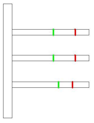
So I called my tech, told him what I found, and worked with him on the phone. Followed his procedures to timing the platter, and told him what I found. Turns out that the card that controls the LED intensity seemed to have gone bad. I was unable to adjust the current for the bottem platter. Atleast I wasn't able to turn it down. I ordered two new cards, and put one in, and voila, problem fixed.
I don't know how we missed that, but all I can say is i'm happy it's over and done with. No more moving prints cause we split the house. I'm going to take a better look at the card tomorrow and see if there is any visable damage next to that trim pot.
Posted by Michael Schaffer (Member # 1204) on 04-06-2006, 05:05 AM:
We all thought you had already tried to retime the platter decks. That anomaly should have been noticed then, then it wouldn't have become such a big "mystery".
Posted by Brad Miller (Member # 2) on 04-06-2006, 10:59 AM:
Fully agreed. Timing the platters includes calibrating the led card. Out of curiosity, what was the ohms rating on the multimeter for the bottom deck that was throwing prints?
Posted by Thomas Dieter (Member # 2507) on 04-06-2006, 11:15 PM:
I was under the impression that we had already tried that.
When I took and pulled the card, I noticed the Ohms setting before pulling it and attempted to set it. On the setting of 20M it was reading 1.25+ I checked the other two decks and they were set at 0.45ohms or there abouts. The Bottom deck would not go any lower than that. I've yet to look at the card I pulled, but it does have brown spot on it.
The techs settings are done at this.
LED Intensity: 0.45OHMs
Low Trim Pot set at 20 Degrees: set to just the point the motor hums or growls.
High Trim Pot set at 70 Degrees: set for 20 RPMs.
Recheck the Low Trim Pot, and tweek as needed.
Recheck the High Trim Pot, and tweek as needed.
I set all the platter to the above settings, and had not 1 single problem today. The Payout worked perfetly, and the take up worked just as good if not better.
[ 04-07-2006, 01:39 AM: Message edited by: Thomas Dieter ]
Posted by Brad Miller (Member # 2) on 04-06-2006, 11:26 PM:
Well your tech is partway there on ideal timing at least.
Posted by Monte L Fullmer (Member # 2797) on 04-08-2006, 02:08 AM:
Thomas - did your tech use a 'platter tach', or just count revolutions of the deck?
Posted by Eric Robinson (Member # 2966) on 04-08-2006, 12:06 PM:
Sorry guys, I'm totally confused.
This implies setting the LED intensity to 70 ohms
quote: Monte L Fullmer
12.6K ohm on the LED resistance? (OUCH!) Should be down to 70 (-/+ 2) ohms with the pointer on the 70 degree mark..and use a digital VOM meter.
-Monte
While the Christie manual specifies 70,000 ohms
quote:
Set film position sensor over 70 degrees mark on feed control plate...
...If necessary, adjust LED intensity to obtain approximately 70 Kohm ...
and now, from this topic we learn
quote: Thomas Dieter
On the setting of 20M it was reading 1.25+ I checked the other two decks and they were set at 0.45ohms or there abouts.
Should I be confused or not?
Posted by Monte L Fullmer (Member # 2797) on 04-08-2006, 02:43 PM:
Okey, so I forgot the "K" in the ohms reading.. ![[Big Grin]](biggrin.gif)
...I go by what the book says...I've never had any probs with using the 70k ohm, 20 and 70 degree settings. .. BUT..
I also have a platter tach to get accurate RPMs per resistance settings..
Monte
Posted by Thomas Dieter (Member # 2507) on 04-08-2006, 03:04 PM:
Monte,
I don't know if he used a "Platter Tachometer", but he did use a Tachometer. No, I myself took and had to count the revolutions by eye. Wasn't that hard, but it did get tedious. Took me about 15 mins to do each theatre, depending on how long it took to set the LED cards.
Eric,
When Monte said the LED card should be set to 70 OHMS, he was refering to 70K OHMS, just like the Christie Manual says. Everyone seems to have their own setting to set Christie Platter cause from the sounds of it, Christie has no idea how to time time as they have changed the setting 3-4 different times.
On my multi-meter, the setting is at 20M, for 450K OHMS at 20 Degrees reads 0.45. When I took the reading of tha card before pulling it, it was reading 1.25 or higher, meaning it was set WAY to high (something like 1250K OHMS), and it wouldn't come down. It would go up, but not down.
--Tom
Posted by Eric Robinson (Member # 2966) on 04-08-2006, 03:52 PM:
Sigh of relief ![[Eek!]](eek.gif)
I had one of those sinking feelings that I had been doing it wrong all this time. It is not uncommon for me to discover this once and a while when reading these forums.
I have been using the Christie method 70K at 70% which seems to work quite well. I use a tachometer and set RPM's to 22 RPM at 70%.
I do have one platter system though; a Christie mini-wind which has caused problems for me since day one despite repeated calibrations, circuit board replacements, variable density, and LED assembly replacements. It seems like it always needs a little fine tuning on the high speed motor pot while its in use. The platter size is smaller too which I take into accomodation when using my RPM gauge.
Posted by Monte L Fullmer (Member # 2797) on 04-09-2006, 02:14 AM:
quote:
I have been using the Christie method 70K at 70% which seems to work quite well. I use a tachometer and set RPM's to 22 RPM at 70%.
This is where the simple mechanical/electrical comes into play with the AW3(r) decks -
1- get the mechanical adjustments set first (which is getting the notch of the shutter to be directly above the edge of the fotosensor by adjusting that small allen situated on the end of the return tang in the platter arm with the cover open..and power off.
2-After this mechanical adustments is made, there is the resistance settings of the LED with the "finger" at the 70 degree mark on the brainplate and having the 70k ohm reading on the VOM - as per instructed in the manual.
3- Then do your lo/hi pot adjustments per the 20 and 70 degree mark on the brainplate with the correct revolutions per setting. (and it really does help with a platter tach, but understand that not everyone has access to one..even though the cost a little over a hundred bucks from Christie..)
If you got "platter creep" even with all that can be done, you've got a good chance of a fotosensor is starting to short out and an easy way to see is when the sensor is taken out of the arm and you look into the glass. If you see black inbetween the wavy lines of the sensor..it's starting to short out. Time for a new one.
Done many AW3(r) platter timings...love these things if you keep them timed just right - and never had any problems with these units..(outside of shortened sensors and just get a sticky motor puk once in a while...lol) with the timing settings above.
-Monte
Posted by Eric Robinson (Member # 2966) on 04-10-2006, 11:26 AM:
I'm not sure I'm following your instruction:
quote: Monte L Fullmer
getting the notch of the shutter to be directly above the edge of the fotosensor
The platters I have worked on have a flat spot on the rod which the variable density filter mounts to. This pretty much defines the rotational position of the variable density filter. I do take a peek into the arm though to make sure the heigth of the variable density filter is such that there are no mechanical conflicts when the brain plate feed out arm is excercised to either extreme as well as the take up arm. I also check to make sure the take up arm white plastic hook is catching the arm on the variable density filter assembly properly. Are there additional adjustments with the variable density filter that I should consider?
Posted by Monte L Fullmer (Member # 2797) on 04-11-2006, 01:33 PM:
quote:
I'm not sure I'm following your instruction:
Sorry on this. Got ahead of myself.
This adjustment gets the "V" notch on the 'wig-wag' arm over the "zero" setting on the brainplate as much as gets the notched edge of the filterdisc above the left edge of the fotosensor.
The black tang that rests against that white "hook" has an allen set screw adjustment there - a real small allen set screw. This is where you make this mechanical adjustment mentioned above.
Posted by Eric Robinson (Member # 2966) on 04-13-2006, 12:09 AM:
Monte - You sound like a pro with these Christie platters.
I was following you on the "wig wag arm", but:
quote: Monte L Fullmer
as much as gets the notched edge of the filterdisc above the left edge of the fotosensor.
I have never seen a notch in the filterdisc. Also the brain plates used in my location have very worn slots in the posts which seat into the platter axle shaft. The mating slot is so sloppy that you can rotate the brain plate to the left and right about 1/2".
On other platters, the pin which mates with the brain plate to keep it in one position have come loose and they slide out of position, allowing the brain plate to spin in circles.
Do you know if this condition is repairable somehow. I have looked into the cost of new platter shaft assemblies and they are quite expensive.
Posted by Monte L Fullmer (Member # 2797) on 04-13-2006, 12:26 PM:
quote: Eric Robinson
have never seen a notch in the filterdisc
If you look right on the edge of the filter disk with the brain in the socket and the brain in in the closed position, it should be there - a round notch.
If you take the sensor out, the return arm out, then pull the platter shaft assembly out, the filter disc will stil be attached to the brain cam shaft..then you can see where I'm coming from.
.and that is what you need - new platter deck shafts...and get those brain plate centers replaced as well that has no pin on them...
Seriously, I actually hate "brain flopping" - moving brains from deck to deck on a continual basis, especially with the AW3 because of the wear that can happen with them if not taken proper care and usage.
This will cure up a lot of your problems..
..like trying to tune up a car with a distributor that won't lock down completely - you're not going to get there.
...can't figure out why those are so worn badly...unless the operators there are so brutal in handling these units...whom should be released immediately.
sorry on this, but misuse is costly. good luck and thx - Monte
Posted by Eric Robinson (Member # 2966) on 04-18-2006, 07:43 PM:
I just had a look into the platter arm today and yes I saw the notch in the variable density filter. This is a good thing to know about.
By the way does anyone know if the red LED sensor is any different than the green LED sensor. I have some older platters with red LED's and have run out of red LED replacements, I have plenty of green though.
Posted by Monte L Fullmer (Member # 2797) on 04-18-2006, 11:53 PM:
I ran both colors..just means a different vintage of sensors, but they do the same task needed.
There is a later version of the sensor,but I'm not familiar with those since I left the theatre that had the AW3's .. and was immediately blessed with adopting STRONG booths from now on.
Posted by Brad Miller (Member # 2) on 04-19-2006, 04:58 AM:
Blessed??? Monte my friend, I'm afraid you have gone senile.
BTW, the red leds are far more stable than the green ones.
Posted by Monte L Fullmer (Member # 2797) on 04-19-2006, 01:20 PM:
..should have put quotes around "blessed" LOL .. since I'm now stuck with these units...-monte
Powered by Infopop Corporation
UBB.classicTM
6.3.1.2