This is topic Solar Cell Preamplifier Design Problem in forum Film Handlers' Forum at Film-Tech Forum ARCHIVE.
To visit this topic, use this URL:
https://ft-forum.com/ft/cgi-bin/ubb/ultimatebb.cgi?ubb=get_topic;f=1;t=007647
Posted by Marin Zorica (Member # 1716) on 11-28-2005, 03:30 PM:
I work on preamp design and now i got something new, but don't working like i was planned :-) , maybe somebody know answer.
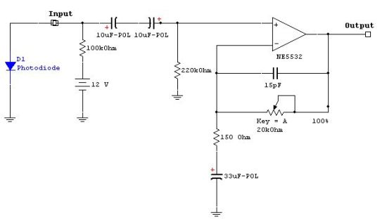
This is schematic of it:

OK, When photodiode is decoupled from preamp with capacitor everything is ok, but when i conected it directly i don't get sound like it should be, i got it but like the wire losing contact or have poor contact, but everything is OK with contact, but is sounding like that (don't know how different i described that sound), and when i put capacitor in serial with photodiode i got ok sound and everything working fine.
I use some polish photodiode 1PP75, because i have it in mine projector sound head in the moment, but that's not problem i think!!
Can you figure what could be problem of this? Did you ever have problem like this?
I also try to change polarity of photodiode but then i got no sound at all, or some poor sound but with same effect.
Tnx!
Posted by Bruce Hansen (Member # 281) on 11-28-2005, 06:09 PM:
Is the photodiode a solar cell, that is, it produces current when light hits it? If so, then this DC voltage will miss bias the op amp, and the output will sit at one of the power supply rails.
Posted by Louis Bornwasser (Member # 3063) on 11-28-2005, 07:11 PM:
Bruce is prob. exactly right. Why not use a suitable capacitor or transformer? Louis
Posted by Steve Guttag (Member # 268) on 11-28-2005, 10:29 PM:
What is the gain of your system? The TL072 will gladly amplify DC too. Whereas your diode will produce volts or current...the op amp will dutifully amplify that to its voltage rail... and that is all she wrote.
Once you block the DC offset from the input...you probably don't need the cap on the output but it is always safer to decouple.
Another thing to consider is that the TL072 may not be the best choice of optical preamp...look for a chip that is more geared towards "microphone preamp". Also, strongly consider going for a differential input design. Unbalanced preamps such as yours are very prone to picking up all sorts of noises and pops.
Steve
Posted by Marin Zorica (Member # 1716) on 11-29-2005, 02:06 AM:
Yes differential input is mine next step, but that's no problem to do with OP amp.
So do you think to put capacitor on input or directly connect cell/photodiode on input?
Is there reason using cell/photodiode?
Also i considering use NE5532 as OP amp
Posted by Gilbert Travin (Member # 2138) on 11-29-2005, 10:05 AM:
Hello, all!
The preamp based on the Tl072 (low cost and low noise op amp) is a current to voltage converter. The solar cell is a current generator. The cell produces always a current because the optical tracks are not entirely black even when nothing is recorded (there is a continuity line to avoid transcient noise (cloc !)). This cell-current is converted to a voltage by the op amp (voltage output is cell-current value times value of the two feedback resistors) : so you have always a DC voltage at output. That's normal you saturate your op amp if resistors value is too high. With capacitor, this phenomena disappears.
The better solution has been suggested supra : using shielded transformer or differential amplifier based on very low noise op amp ! Good luck ![[Wink]](wink.gif)
Posted by Louis Bornwasser (Member # 3063) on 11-29-2005, 10:49 AM:
Some mention should be made of the value of a L.F.rolloff. Very low frequencies will allow the shutter (or its modern equivalent) to thump each time it opens. Suggest you dump everying below 60 hz or so. Most transformers have some losses about there. Louis
Posted by Phil Hill (Member # 371) on 11-29-2005, 05:40 PM:
I would never use an input/coupling transformer in that application. You'd still have the same DC bias problem that could saturate the transformer and still need the isolating/coupling cap. Besides, they usually have crappy freq response unless you spend big $ for one.
I would leave it as single-ended, unbalanced input with the cap unless you have a hum problem. I'd add a 2-3k load resistor across the PC.
I do agree that you need some LF ***AND*** HF roll-off RC networks in the OPAMP feedback loop.
While I haven't looked at the manual section, you might want to look there at some schematics to get some ideas. ![[beer]](graemlins/beer.gif)
Good luck.
Posted by Mark Gulbrandsen (Member # 72) on 11-29-2005, 09:43 PM:
With an op amp the gain is determined by R-1/R-2. For a gain of 40 db which is typical for a mic preamp. The pot would be R-1 and there would also be a resistor from the - input (with one end of the pot) of the opamp to ground called R-2. Divide R-1 by R-2 to get the gain of the circuit. Say that R-2 is 10k and R-1 (the pot) is 100K... 100/10 = a gain of 10. Try 75K for R-1 and 2.2K for R-2, a gain of about 37. Also you want to have the photo diode feed the + input, not the - input... Feeding the photo diode in the - input will invert the signal... it will be out of phase with the input.... Use the cheap TL-072 chips to experiment with and when you get it right pick a high quality Burr-Brown chip with high snr and good slew rate. Burr Brown and Analog Devces make some of the best op-amps out there.
If anyone here finds that my math or theory is wrong please let us know.... Math is not my forte...... Its also been a long time since I messed withh op-amps... I've since converted over to using vacuum tubes.....
Mark
Posted by Marin Zorica (Member # 1716) on 11-30-2005, 03:18 AM:
¸Mark, i know what you thinking to do but, in mine circuiot we have virtulay zerro efect on input, that means input impendance is close to 0 because +input of OP amp is conected directly to earth, this is because photodiode or cell must be threated as curent source to get lovest distorzion, is this wright?
But after this comes HF EQ circuit which also got input on -in of OP amp so finaly we get signal in phase!
Here we also could use Mark relation for Gain calculation if we put resistor in serial with photodiode input, but small resistor of about 100ohm
Can eneyone got schematic of CP45 preamp or something newerlike that, i would like to saw it how is based? Because in manual section there only circuit with transformer.
Posted by Gilbert Travin (Member # 2138) on 12-01-2005, 02:38 AM:
Marin
Your circuit is a current to voltage converter and its input impedance is very low : that's a good solution with a solar cell (a current generator needs a very low loading impedance). The circuit discribed by Mark is (I think ) an inverter : you can obtain a low input-impedance with R1 = 100 Ohms (and R2 = Gain x R1). But you have always the off-set problem (and saturation if gain is too high ....)
A very good transformer (such as CP 50) is not cheap. This subject has been discussed on this forum and Gordon had given an answer ![[Smile]](smile.gif)
If you use a photodiode, you must bias it (reverse current obtained with a DC source and a resistor).
Posted by Marin Zorica (Member # 1716) on 12-01-2005, 04:17 AM:
I was thinking that photo diode and solar cell got similar characteristic, ok if i use solar cell you think this preamp would work ok?
With photo diode i already use bias voltage, when i get home i draw schematic of that solution and upload it.
Does de coupling capacitor on input effect on input impedance much?
Posted by Gilbert Travin (Member # 2138) on 12-01-2005, 04:40 AM:
Marin ;
I think it is better to use solar cell (a solar cell don't need biasing and gives a higher and noiseless signal than photodiode).
With your scheme, you risk saturation because of DC current : you must use a coupling capacitor (i.e. 1 uF) or compensate DC off-set with a DC source and a trimmer. The preamp-diagram becomes then more complicated !
Posted by Marin Zorica (Member # 1716) on 12-01-2005, 10:59 AM:
Then capacitor is simpler choice if result is same :-)!
When i get home i will hook-up some solar cell in projector sound head and try same schematic with it, can't wait to hear difference!
Can i use some other solar cell except cell for soundhead?
Posted by Louis Bornwasser (Member # 3063) on 12-01-2005, 07:06 PM:
Use an op-amp labs 350p optical preamp. Low cost and mountable in octal based "tube." This is a mike level preamp widely used for amplifying a solar cell output; especially in the pre-Dolby era. Louis
Posted by Phil Hill (Member # 371) on 12-01-2005, 07:20 PM:
Marin, as I said before AND you seemed to poo-poo and ignore... I ***STILL*** recommend to quit F*CKING around with the so-call "experts" and look at the FT manual section. Specifically the SMART manuals.
They have manuals that include schematics that are not only cleaver and efficient, but also follow good engineering practices and use the "proper" parts and component values. Some really good stuff. Oscar and his team REALLY knew their stuff!
OBTW: Scrap the photo diode and use a cell as others have suggested.
AGAIN! Good Luck!
Posted by Marin Zorica (Member # 1716) on 12-02-2005, 03:31 AM:
Yes, planing to go with cell, but here stereo solar cell with bracket cost $300, so isn't so cheap for experiments.
I look at manual section and smart only got schematic at old stuff, not on newer.
But i'm think i'm on wright way to get some good preamp.
Posted by Phil Hill (Member # 371) on 12-02-2005, 03:49 AM:
Holy Smokes! $300 for the cell and mount? What projector are you building this for?
Smart may have newer stuff listed on their website in the manual section. BUT! There is nothing wrong with their older stuff... I think they made a mono optical preamp, now discontinued, that was very simple and reliable.
Posted by Marin Zorica (Member # 1716) on 12-02-2005, 06:13 PM:
OK, it's 255$ ![[Razz]](tongue.gif)
It's for prexer or Iskra (ernemann 7, 8) but price is same.
Gonna look manuals!
Posted by Marin Zorica (Member # 1716) on 12-07-2005, 07:28 AM:
I try some kinds of other designs and solar cells in sound head but still i need decoupling capacitor at cell input.
Can be this does without it? And how decoupling capacitor effect on signal and frequency response?
Posted by Robert Minichino (Member # 3495) on 12-07-2005, 07:43 AM:
Since there is a DC offset on the solar cell output you will need some way of eliminating this; a DC-blocking capacitor is the easiest way. If it's appropriately sized it will roll off only very low frequencies (below, say, 20 Hz) and have no audible effect. I'd use a bipolar electrolytic bypassed (in parallel with) with a small-value (0.1uF) mylar or polypropylene cap.
An alternative is to use a DC servo. This is an amplifier with a low-pass on its input, and you mix its output in with your signal to zero-out the DC offset in the signal. This way the signal never passes through a capacitor, but it's too complex in my opinion.
Posted by Marin Zorica (Member # 1716) on 12-07-2005, 10:16 AM:
quote: Robert Minichino
I'd use a bipolar electrolytic bypassed (in parallel with) with a small-value (0.1uF) mylar or polypropylene cap
Robert,
can you tell what is that bipolar cap. you use in paralell with this of 0,1uF?
Posted by Robert Minichino (Member # 3495) on 12-07-2005, 11:12 AM:
A bipolar electrolytic capacitor is like having two electrolytic capacitors connected back-to-back in series; these are often used in speaker crossovers.
I don't think you really need one, though. A regular polarized electrolytic capacitor should be fine in this application as the cell works like a diode anyway. Sorry for any confusion.
A small value high-quality capacitor in parallel with a large electrolytic won't change the total value much, but it will mean that any high-frequency signals that the electrolytic might not pass well (due to internal inductance, for example) will pass through the small film capacitor instead.
You probably don't even need the film bypass capacitor as most electrolytics should be fine in the audible frequency range, but I have a big box of them so I don't mind adding the parts for my own circuits.
Posted by Mark Gulbrandsen (Member # 72) on 12-07-2005, 05:38 PM:
quote: Phil Hill
Marin, as I said before AND you seemed to poo-poo and ignore... I ***STILL*** recommend to quit F*CKING around with the so-call "experts" and look at the FT manual section. Specifically the SMART manuals.
Marin,
It is sad that there are people here that seemingly want to discourage you from the learing process ***AND*** bettering yourself. One learns absolutely nothing by simply copying an existing design, and some of those designs are ***VERY*** inferior to what you could build yourself. I personally encourage you to proceed down the road you were on and learn all that you can on your own ![[thumbsup]](graemlins/thumbsup.gif) It'll make you a much stonger, more valualable person in the long run.
It'll make you a much stonger, more valualable person in the long run.
For more help down ***Your*** road I reccomend the DIY AUDIO WEB SITE . There are ***ALOT*** of very gracious, friendly people, and many degreed electrical engineers that would be glad to help you out.
Mark
Posted by Marin Zorica (Member # 1716) on 12-08-2005, 05:35 AM:
quote: Mark Gulbrandsen
It is sad that there are people here that seemingly want to discourage you from the learing process ***AND*** bettering yourself.
Thanks for this Mark!!!
Yes i know for DIY Audio and i'm already there!
Posted by Gordon McLeod (Member # 33) on 12-08-2005, 05:52 AM:
I don't think anyone is actually putting anyone down
But I think Phils advice is very valid of dropping the photodiode and using a solar cell
Also there is little point ion reengineering the preamp design as most of it has been researched to death
There are some nice prepackaged mic preamp chips (I believe in the SSM line) that work very well
Posted by Marin Zorica (Member # 1716) on 12-08-2005, 10:53 AM:
quote:
I think Phils advice is very valid of dropping the photo diode and using a solar cell
Hmm $255 for cell with bracket i think is expensive!
Also could somebody described difference between solar cell and photo diode?
I know guy whose working also what I'm doing, and he told me that he didn't noticed any difference between solar cells and photo diode, he install CP200 and try to put photo diode and solar cell for comparing and say that didn't get any difference.
What you think?
Posted by Richard Fowler (Member # 893) on 12-08-2005, 11:24 AM:
Raw stereo cells are $30 to $80.00 depending on type....machine or modify your bracket I noticed Eastern European and Russian machines favor photo diode set ups.
Posted by Phil Hill (Member # 371) on 12-09-2005, 12:39 AM:
Oh Mark! You're such a brute. ![[uhoh]](graemlins/uhoh.gif) I never said what YOU said I did! Get off the I-30 stuff! You REALLY need to go back to reading comprehension 101 before you yap as some holy know-it-all.
I never said what YOU said I did! Get off the I-30 stuff! You REALLY need to go back to reading comprehension 101 before you yap as some holy know-it-all.
As usual, you spout off before reading and comprehending what was/has been said. Perhaps you should hold your comments until YOU read ALL the previous comments in the thread.
Go back and re-read this thread. I only ***suggested*** that Marin LOOK at those schematics for ***IDEAS***. I NEVER said to COPY the circuits. JFC!
BTW Mark: Many others, including myself have posted several times here about improving his design considerations. It really gets ***F*CKING*** annoying that HE keeps asking the **same** question over and over again EVEN after HIS questions have been answered by many including myself. It appears that HE is not taking the advice of the FT members or is just DENSE.
Mark, get off your high-horse. It's an insult to MANY FT members that YOU think there are BETTER "qualified" people (electrical engineers, techs, etc) elsewhere just points to insulting the talent here.
quote: Marin Zorica
quote=Gordon McLeod
"I think Phils advice is very valid of dropping the photo diode and using a solar cell"
Hmm $255 for cell with bracket i think is expensive!
Marin, perhaps YOU should take up another HOBBY!
OBTW Marin: I have NO idea as to what that cell assembly costs and was just amazed at what you said. BUT! You apparently took my inquire wrong.
Re Marks post:
quote: Kiss Kiss Marin Zorica
Thanks for this Mark!!!
Just like Mark, Marin YOU NEED to read ALL of this thread...especially before you stick your nose up his butt!
I was only asking about what projector since I had a spare SIMPLEX cell I would be willing to send you free.
Perhaps Mark in his limitless experience, knowledge, ignorance, usual arrogance, and vast stock of parts would be willing to send you one free to help you out? If not, I still offer my Simplex cell. NO Charge.
[ 12-09-2005, 03:17 AM: Message edited by: Phil Hill ]
Posted by Marin Zorica (Member # 1716) on 12-09-2005, 07:00 AM:
First of all we ***MUST*** stop with all this hard words!!
Phill, don't mean to upset you, i know why you advice me for using solar cell, and if you have one for give me I'll be glad to get it from you, also i was little bit more for photo diodes, because they are cheaper and you may get it everywhere, and like Richard said in Eastern European projectors there are mostly used photo diodes, and here i servicing that machines, because there are plenty of them.
Posted by Mark Gulbrandsen (Member # 72) on 12-09-2005, 08:34 AM:
quote: Phil Hill
Mark, get off your high-horse. It's an insult to MANY FT members that YOU think there are BETTER "qualified" people (electrical engineers, techs, etc) elsewhere just points to insulting the talent here.
Phil,
Sorry bud but that is the truth. Smart F-T members already know that. If its audio design Marin wants to learn this is DEFINATELY NOT the place to learn it!
There is only one degreed electrical engineer around here that I am aware of that really knows his stuff... and is sometimes willing to share his knowledge with us. There are more than I can count over there and many with decades of experience in every facet of audio design. Several of the audio industries top engineers hang out over there... people like Erno Borbley, John Curl, Nelson Pass, Jan Didden, and a bunch of others, yes these guys also design your beloved "commercial" stuff as well. If you wouldn't want your questions answered and your designs tweeked by these guys fine, I guess you know more than they do.... but for the rest of us that know who these guys are it's a priveledge to have contact with them.
Mark
Posted by John Pytlak (Member # 331) on 12-09-2005, 02:46 PM:
I'm one of many degreed electrical engineers who participate on Film-Tech, but it's been years since I've had to design any electronic circuit for a living. The experts in designing audio amplifiers are the ones who do it for a living, and have their designs proven by success and reputation in the market. A BSEE is only the beginning. Experience is the real education.
Posted by Mark Gulbrandsen (Member # 72) on 12-09-2005, 05:16 PM:
quote: John Pytlak
Experience is the real education.
Well put John! And thats rally the only way Marin is going to learn... copying someone elses design doesn't really ause much brain growth. Its interesting that you atarted out with a BSEE.... How on earth did did you go from electrical engineering to making film at Kodak?
Mark
Posted by Phil Hill (Member # 371) on 12-12-2005, 06:47 PM:
Marin, please re-send me your email directly to my private email and include your addr so I can send you the cell as you requested.
(Sorry, I don't know how to reply thru FT and insure you get my response.)
Posted by John Pytlak (Member # 331) on 12-14-2005, 10:49 AM:
quote: Mark Gulbrandsen
Its interesting that you atarted out with a BSEE.... How on earth did did you go from electrical engineering to making film at Kodak?
The transition is easy, and many Kodak film engineers have backgrounds in electronics. Lots of image science has its roots in electronics and communication theory. The work of Nyquist, Maxwell, Fourier, Schade, and their successors are well known and often used in image science. And since the majority of Kodak's revenue now comes from digital imaging, EE's and IT's are in ever increasing demand at Kodak.
Posted by Mark Gulbrandsen (Member # 72) on 12-15-2005, 11:24 AM:
That interesting John, I never would have thought the works of those guys would have anything at all to do with film... but then I never studied how film is made to any great extent, just how to use it.
Thanks!
Mark
Posted by John Pytlak (Member # 331) on 12-15-2005, 11:42 AM:
A film latent image is formed by electron transfer:
http://wwwcaen.kodak.com/US/en/motion/products/v2/2electron.shtml
quote:
In Kodak’s two-electron sensitization scheme, an appropriately designed electron donor molecule, X–Y is added to the photographic dispersion. This molecule transfers an electron to the oxidized dye to give a radical cation, X–Y•+. The radical cation then undergoes a fragmentation reaction to give a radical X•, and a stable cation, Y+.
The radical X• can inject an electron into the silver halide conduction band. In this way, the oxidized dye, which is a strong oxidant, is replaced by the radical, X•, which is a strong reductant. Thus, the two-electron transfer scheme has the potential of doubling the photographic speed because two electrons are injected per absorbed photon.
Film has many similarities to solid state electronics. But it makes better images.
Posted by Marin Zorica (Member # 1716) on 12-18-2005, 08:44 AM:
Thanky you for all answer, it's help me a lot!
Ok, you probably all know reason why i work with photodiodes (untill i get phil's cell :-) ).
This is schematic of preamp with photodiode and photodiode is biased with DC voltage.
What you think what level of biasing voltage, measuren on input rail could be wright for minimum distorzion, and does distpruion concidering of a bias voltage???
Posted by Marin Zorica (Member # 1716) on 12-19-2005, 03:33 PM:
No comments?
Posted by Steve Guttag (Member # 268) on 12-19-2005, 05:10 PM:
So Mark...I know I'm one of the degreed Electrical Engineers over here...however, as John has said, experience is where it is at when it comes to good designs. Sure, one must have some sort of raw talent and proper education to use that talent but one must play with it a bit to get really good.
Perhaps you are thinking of Ray Derrick? I suspect he is a double-E and certainly knows his stuff. I'm pretty sure Oscar is not a double-E yet also seems to know his stuff.
Who is the EE you are thinking about?
As to designs...there is nothing wrong with looking at what has been done to get one started. It is pointless to regurgitate an existing design (and also violates copyrights). Presumably the reason for a new design is a desired design does not exist or exist in a form you need it.
As to the design as it stands...I would get away from the single-ended stuff...you WILL have noise in the system from ticks and pops. I would also limit the frequency response going into your op amp with a single pole low-pass filter. Your HPF probably doesn't need the second cap in that with a 12V power supply you probably will never have the cap reverse polarized. Also look into the lowest frequency you will possibly need (there is going to be mostly noise and crap down there) and use the blocking capacitor as your first HPF.
Your adjustable gain section could also use some work. What is the range you really need? Again, what is the frequency range you really need?
Do you have any simulation software? You might find it interesting to first simulate your circuit before building it to get all of the particulars set. Sweep the frequency and make sure you have something that is stable before you hook speakers that might suffer first.
Posted by Marin Zorica (Member # 1716) on 12-19-2005, 05:59 PM:
Thanks Steve!
Yes i know for response limiting, but mostly on this circuit i want to know about photo diode DC bias!
A know all ready about cell and stuff, but this is situation i have so please HELP!
Is it possible to obtain good sound with photo diode??, off course properly biased. Mostly i thinking about low distortion, because freq. response isn't problem. I can upgrade this adding regulative resistor so i can change DC bias voltage, i put 100K resistor on DC bias to save photo diode for over current, it that ok?
What's HPF???
Posted by Steve Guttag (Member # 268) on 12-19-2005, 07:44 PM:
Sorry...HPF = High Pass Filter.
As to the photo-diode...I have no personal experience in properly setting one up (except maybe in a physics class many moons ago) thus I would hesitate to advise you on that part of the circuit.
Posted by Mark Gulbrandsen (Member # 72) on 12-19-2005, 10:44 PM:
quote: Steve Guttag
Who is the EE you are thinking about?
Indeed Ray is the first one that comes to mind that has posted on these forums, but is rarely here any longer, most likely just too busy as most highly qualified people of his type are. Oscar would also be a good choice and he has also had sucessful products over the years. Other than these two I can't think of any analog designers that have frequented this forum that have had truely sucessful products. Ray in my mind is without doubt the most sucessful analog-cinema designer that I know of. Oscar also comes to mind but is Oscar still with us? I heard from another member that he is now with Leviton. All the other people that I mentioned back in the other post are also all highly sucessful engineers that have all developed multiple highly sucessful product lines in varying audio fields over the years. Some of them also have other pertaining dergrees. Between those people there are easily over 300 collective years of audio design, perhaps more.... and they are all accessable through DIY. I am sure that both Ray and Oscar either know some of those people or certainly know of them. A few of them have also made contributions to cinema audio over the years. Marin is aware of that and is also a member over there. Its the best place I know of on the net to learn about designing circuits of just about any type.... The hits that site gets daily is staggering and you are very likely able to get assistance from some of the top engineers in audio on a project over there.
As for looking at others designs.... thats pretty much a given. Anyone with any ounce of interest in how things work are going to do that. Some of us look at the design and schematics in order to enable us to better utilize a product. You can certainly learn about different topologies and types of designs by looking at schematics. However, looking at topologies and others designs doesn't teach you HOW to design. What I read in between the lines in Marins original post and what Marin later confirmed was a desire to learn how to design a circuit. Reading books, going to school, and above all experimentation and achieveing the results you projected are whats going to teach you how. Its completely up to an individual to carry that out to what ever level he/she is interested in taking it to.
On the balanced issue I couldn't agree more. Noise will always be an issue with a single ended circuit, especially in a noisy environment like the typical booth. Its either going to require a transformer input, or a true balanced circuit to get to the right place. This could be implemented with IC's or discrete circuitry but the latter would take quite a bit of work. In fact there is an interesting paper over at Jensen Transfomrers that is good reading on this subject. Another very unique circuit designed and patented that would make a great cell preamp is the Super Symetric fully balanced/cross coupled circuit. This patented circuit and many other patented circuits are available for non profit use by permission of their designers for members over at DIY. I have built line level circuits based on this patent that are pretty amazing. BTW: this circuit is fully capable of either low level work or power amplifier work. Because this circuit has so many exceptional qualities there has also been much interest in turning this circuit into IC form and this may be happenning sometime in the near future.
I have to chuckle.... Even though one member here claims that the solor call preamp "has been researched to death" it would appear to me that it really hasn't been.
Mark
Powered by Infopop Corporation
UBB.classicTM
6.3.1.2