This is topic Neumade platter brain wiring issue in forum Film Handlers' Forum at Film-Tech Forum ARCHIVE.
To visit this topic, use this URL:
https://ft-forum.com/ft/cgi-bin/ubb/ultimatebb.cgi?ubb=get_topic;f=1;t=008074
Posted by Cory Isemann (Member # 2517) on 06-11-2006, 10:40 AM:
Ordered some emitter-detector boards from Neumade a few months back and never got a good look at it until today... there are 4 solder points on the newer board, but only 3 on the older one. Will one of these points be unused or will it need to be jumpered? I can't upload the pictures right now, but is anyone familiar with this?
Edit: add shitty picture
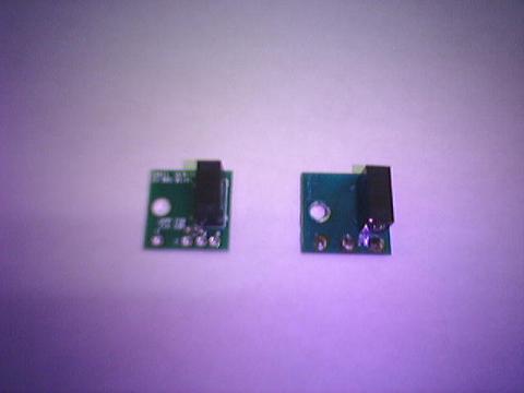
New one on the left, old on the right.
[ 06-12-2006, 10:20 AM: Message edited by: Cory Isemann ]
Posted by Stephen Frazza (Member # 2320) on 06-12-2006, 01:23 AM:
The same thing happened to me about a year ago and I just called Neumade and they gave me the answer. But I can't remember what that answer is right now.
I don't work again for a few days but if you still need a answer by then I'll open up one of my brains and let you know.
Posted by John Walsh (Member # 168) on 06-14-2006, 04:32 PM:
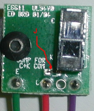
The hookup is the same. The sensor itself has four terminals. Two for the IR LED, ("A" anode and "K" cathode) - and two for the photo 'receiver' ("C" and "E".) On the old board, "C" and "K" are connected together by a copper trace. On the new board, there is a little jumper (shown in picture pointed at by "J") that connects "C" and "K".
Posted by Cory Isemann (Member # 2517) on 06-15-2006, 02:04 PM:
Thanks John..So pretty much you're skipping that third contact.. wire colors still in the same order too? It would seem so.
Powered by Infopop Corporation
UBB.classicTM
6.3.1.2