This is topic Meopta Rectifier Schematic Question in forum Film Handlers' Forum at Film-Tech Forum ARCHIVE.
To visit this topic, use this URL:
https://ft-forum.com/ft/cgi-bin/ubb/ultimatebb.cgi?ubb=get_topic;f=1;t=008272
Posted by Marin Zorica (Member # 1716) on 09-24-2006, 01:13 PM:
This is schematic of that rectifier:
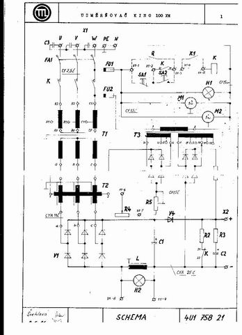
So, question is what V4 diode is for? Is it just for safety measures if someone switch poles on XBO so lamp won't ignite or some other reasons? Like maybe got something with that 100V DC coming from other transformers via 300Ohm resistor which is used for lamp striking??
Also something about capacitors C1 and C2...C1 is connected directly and C2 is connected to DC via R3 (for current limiting thrue C2 isn't it?), but why C1 isn't concted via some resistor like C2??? Is this resistor really need to be here???
Also what is R2 for (intended to don't leave DC without load when XBO isn't ON) but how when K switch depress when we switch ON rectifier???
Thanks for answers!!!!!!
Posted by Steve Guttag (Member # 268) on 09-24-2006, 08:24 PM:
Your schematic is very crude in the resolution it was uploaded....
However, Diode V4 is a blocking diode to allow the boost function to work for lamp ignition. Since the boost circuit will charge to a higher voltage to trigger an auto-ignite system (typically 85VDC or higher, the diode will become reversed biased to keep the main supply that is operating closer to 25VDC off line until the arc is established. Once the lamp ignites and the arc is going, the current will cause the Diode V4 to be forward biased so the main supply is powering the lamp...in the event the lamp flames out (cold, worn out...etc), the boost circuit will once again charge things up to a higher voltage due to V4.
C2 is, no doubt a large capacitor or a multiple capacitors that form a large capacitor. Capacitance ranges a bit from 6000uF up to 3 times that, depending on that design. Due to the nature of capacitors and how charges flow through them, a capacitor that is not charged appears as a dead short once current is applied...as the charge fills up the capacitor, its impedence tends towards an open circuit. However, to avoid this short circuit appearance, R3, probably a high-wattage but low resistance resistor is there to buffer the short when the contactor turns on.
C1 is probably a very low value capacitor...probably on the order of .01uF or so whose purpose is to shunt off any high frequency noise and spikes. Should it have a resistor? If you follow math and electronic theory, the answer is yes. however, any resistance will reduce the effectiveness of it functioning as a surge/spike supressor. Practical applications dictate that the resistor is omitted. In fact, many rectifier manufacturers omit the resistor that feeds the main capacitor(s)....better designs don't do that.
R2 most likely bleeds the charge on the capacitor. Most designs do not have a relay to switch the bleed resistor out since a bleed resistor need not be very low in resistance...5K-10K will do. The idea is to drain the charge away...it need not be instantly...just in a reasonably amount of time to avoid someone from being shocked.
Posted by Dave Macaulay (Member # 813) on 09-24-2006, 08:26 PM:
This is a pretty poor image of the schematic, and it uses some icons I'm not familiar with - the transformer icons look plenty strange. Is T1 an isolation transformer and T2 an autotransformer?
T2 seems to provide the main power supply, charging C1 through the choke L. Y4 isolates the boost supply which comprises part of T3 and the diode bridge on the far right. The bridge to its left, I dunno. The boost supply gives a high no-load voltage to provide a strong starting current and to activate auto-ignite circuits. R3 limits the starting current a bit. I think R2 is in circuit when the contactor is open, discharging the potentially lethal voltage from C2. Whew, an electical pun!
Posted by Gordon McLeod (Member # 33) on 09-24-2006, 10:27 PM:
Looks a lot like some of the IREM rectifiers
Posted by Marin Zorica (Member # 1716) on 09-25-2006, 03:37 AM:
OK, yes I know for low resolution but image size is limited by upload.
Here T1 is main three-phase transformer, T2 isn't transformer, is transductor for regulation of output current (when we let higher current thru, we got bigger magnetic resistance, and then we got lower current thrue transducer and due to that lower DC to lamp), and T3 is auxiliary transformer for powering transducer and booster circuit.
What about I remove V4 diode and put booster 100V direct do Dc feed to lamp? Also I put relay which cut off booster voltage when lamp strikes, I try this and work!!! Any opinion about this kind?
Also C1 and C2 are 2200uF capacitors.
Posted by Gordon McLeod (Member # 33) on 09-25-2006, 06:07 AM:
You need to decouple the two parts of the supply
A relay will do it but if it stays on line too long there will be smoke
Posted by Marin Zorica (Member # 1716) on 09-25-2006, 08:24 AM:
quote: Gordon McLeod
You need to decouple the two parts of the supply
A relay will do it but if it stays on line too long there will be smoke
I understand that, but also I put 300Ohm resistor in series with auxiliary power (100V) and I see no heating when is NO-LOAD situation in rectifier. This one is strange....i try to put diode also (like V4 in schematic) but then I can strike the bulb, bulb just won't strike! Strange....
Posted by Dave Macaulay (Member # 813) on 09-25-2006, 12:46 PM:
V4 keeps the boost supply from charging C1 up to the 100V open circuit voltage, that's pretty much all it does. If C1 does charge that high, you will have a VERY high inrush current on lamp ignition.
There's no value on R3, it is probably quite low and limits the inrush current from C2.
You won't have damage in the rectifier by removing V4 unless C1 has a lower voltage rating than the boosted voltage. You may damage the lamp from high inrush current.
R2 is just discharging the rectifier via the normally closed contact on the main contactor K. I don't understand your question about it I guess.
Anyway, does it work as is? Why are you fiddling with it? It sounds like it doesnt work with V4 in there, if so I would check C1 as it probably has lost value and is no longer 2200 uF. When this capacitor is no good, the lamp will flash but not stay on. The choke resists change in circuit current; the capacitor has to supply enough energy to allow time for the choke to let the main power circuit current rise.
Posted by Marin Zorica (Member # 1716) on 09-25-2006, 03:16 PM:
I do everything including V4, but I don't use three-phase transformer like on schematic, I use single-phase transformer. Also C1 is very hot when I strike lamp!!!!!!
Posted by Robert Minichino (Member # 3495) on 09-25-2006, 03:25 PM:
There will be MUCH more ripple from rectified 1 phase AC than 3 phase; have you made any other modifications to compensate for this?
Posted by Dave Macaulay (Member # 813) on 09-25-2006, 09:13 PM:
Unless I misunderstand, you're using a 3-phase rectifier on single phase? Not a good idea.
C1 would get hot because it runs very high AC current trying to smooth out the ripple from single phase. Choke L should be much larger for single phase operation. The lamp power ripple will likely still be way over the specified maximum.
A single phase rectifier compared to 3-phase usually has a huge choke and much higher value capacitors.
Maybe if you use sveral larger capacitors - for about 20,000 uF -or at least remove the series resistor from C2 you might succeed.
The diodes will only be good for about 2/3 of the original rated power as you can only be using 4 of the 6 on single phase.
Posted by Michael Schaffer (Member # 1204) on 09-26-2006, 02:51 AM:
quote: Gordon McLeod
Looks a lot like some of the IREM rectifiers
Indeed it does...And there is probably a reason for that! While our friends in the (former) Eastern Block rejected all political ideals of the West, they weren't as picky when it came to be "inspired" by Western technology... ![[Big Grin]](biggrin.gif)
Posted by Dave Macaulay (Member # 813) on 09-27-2006, 10:38 AM:
Irem uses a manually adjusted main power transformer, where you move a core piece in and out to adjust the transformer efficiency and the output current. Irem has a different way of connecting the diodes, too: on the schematic it looks more like 3 separate single phase rectifiers connected together than a 3 phase bridge. This lets them use 6 identical diodes rather than mix forward and reverse types.
This Meopta uses a saturable reactor. The Japanese Sanrex are the only other cinema rectifiers I'm familiar with that use saturable reactors, I think all Sanrex types do (even the giant 30kW one at Ontario Place).
Plus (but not really standard cinema types) the high reactance Imax 15kW Miller rectifiers, and I think Christie had a 7kW model made by Miller that was likely similar.
Posted by Richard Fowler (Member # 893) on 09-27-2006, 10:54 AM:
The standard rectifier from Proyecson - Spain also utilize a saturable reactor circuit which if you are also using their lamphouse, it is mounted on the lamphouse panel.
Posted by Michael Schaffer (Member # 1204) on 09-27-2006, 04:11 PM:
Dave, where do you see the saturable reactor in the drawing?
Posted by Gordon McLeod (Member # 33) on 09-27-2006, 04:18 PM:
T1 is a saturable core transformer just like the IREM
and the 6 diode bridge and the boost circuit is classic IREM
Posted by Marin Zorica (Member # 1716) on 09-27-2006, 05:07 PM:
quote: Gordon McLeod
T1 is a saturable core transformer just like the IREM
and the 6 diode bridge and the boost circuit is classic IREM
OK, also ISKRA was producing rectifiers like this (6 diodes, and three-phase transformer in star winding), only they didn't put boost circuit. That was in 60's! That are unbreakable�e rectifiers, may bee diode blow after 20 year or so..... ![[Smile]](smile.gif)
Posted by Michael Schaffer (Member # 1204) on 09-27-2006, 06:53 PM:
Is the partially visible line between the transformer coils supposed to represent the saturable core? I can hardly tell what it is supposed to be.
Posted by Phil Hill (Member # 371) on 09-27-2006, 07:08 PM:
At less than 350 pixel width, the schematic pic is uploaded at WAY less than the 550 pixel limit. It sure would help IF we all can see ALL the connecting lines AND DETAIL in the schematic!
Please upload a CLEAR and DETAILED pic!!
Posted by Dave Macaulay (Member # 813) on 09-27-2006, 08:58 PM:
Michael:
T2 is the saturable reactor (he calls it a transductor), and the saturating current power supply is from T3 - the bridge on the left, the right one is the boost power. R4 and R5 are the current controls, probably R4 is in the lamphouse and R5 sets the maximum.
Horizontal lines didn't come out well on the image, you have to guess a bit where they are.
Gord - T1 is a normal power transformer, looks to have a low and high voltage tapped primary.
A 3 phase bridge with 6 diodes is hardly an Irem idea, and Irem wires it rather differently - presumably to use 6 identical diodes and one heat sink.
Posted by Marin Zorica (Member # 1716) on 09-28-2006, 12:45 AM:
T1 is main three-phase transformer, after him power goes to diode bridge V1 true T2 which is transducer for current regulation (current is regulated with current true transducer T2, which current is regulated by resistor R4 from auxiliary transformer T3.
Then we got DC of cca 32V at C1, after that goes boost circuit with auxiliary 100V for firing XBO lamp from T3....and that's all, actually is very simple thing!
Also H2 lamp is on rectifier like warning of over range current!
quote:
Please upload a CLEAR and DETAILED pic!!
I will first thing when I get home! ![[beer]](graemlins/beer.gif)
Powered by Infopop Corporation
UBB.classicTM
6.3.1.2