This is topic Lamphouse Air Temperature in forum Film Handlers' Forum at Film-Tech Forum ARCHIVE.
To visit this topic, use this URL:
https://ft-forum.com/ft/cgi-bin/ubb/ultimatebb.cgi?ubb=get_topic;f=1;t=008742
Posted by Richard May (Member # 2627) on 05-31-2007, 04:37 PM:
Since we are on the topic of lamp exhaust, has anyone actually measured the air temp coming out of the top of the lamphouse? I know there are many variables including lamp size, amperage, etc..
Posted by John Pytlak (Member # 331) on 05-31-2007, 04:41 PM:
My guide is that if the exhaust duct is too hot to touch comfortably, you are likely overheating.
Posted by Steve Guttag (Member # 268) on 05-31-2007, 05:16 PM:
I'm wondering if there is any place that lists the actual amounts of Ozone or other harmful elements coming out of an exhaust stack using a typical CURRENT "Ozone Free" lamp...for say a 2K-6K lamp.
It would also be nice to know how much one can derate the heat load presented to the projection room based on the amount of air flow going up the exhaust stack.
Steve
Posted by John Hawkinson (Member # 1135) on 05-31-2007, 06:26 PM:
Oddly enough, I was doing that this morning, and got 110F for a 2k in a Xetron XHN2000.
Osram specs the anode base temperature at 230 degrees C (446 degrees F), which is not at all the same thing as the air temperature (see p. 25 of the
XBO Theatre Lamps: Technology and Applications guide.).
On the ozone issue, p.33 would you believe that OFR really is "ozone free":
quote:
An electric discharge in xenon gas generates a spectrum ranging from about 140nm in the UV region to far into the infrared region. If the quartz glass bulb is transparent between at least 180 and 220 nm in the UV region, this radiation converts a small proportion of the atmospheric oxygen (O2) into ozone (O3). Ozone is itself a colorless, odorless gas (what you can smell are the reaction products of ozone as it attacks air-borne pollutants and nitrogen compounds); it is extremely aggressive and will damage your lungs if inhaled at relatively high concentrations over a long period of time.
Ozone emission can be suppressed by using quartz glass which absorbs radiation in the relevant UV region. The result is "ozone-free" lamps, which have the letters "OFR" added to their lamp designation. The quartz glass used is either bulk doped or suitably coated. See the UV radiation output in Fig. 33
Occasionally, even ozone-free lamps give off an "ozone scent" shortly after ignition. This has two possible causes: the ozone is produced either as a result of the (temporary) radiation of the spark gap used for ignition, or from the fact that when the quartz bulb is in the cold state the absorption edge can shift and small amounts of ozone-producing radiation can leave the bulb. Both effects cease once the lamp has started up and are cause of no significance.
Tangentially, I was wondering how involved it is to add a booster supply to an existing rectifier whose no-load voltage is a bit on the low side for striking (an IREM P1-X80 driving a 2K lamp; it just barely makes 80VDC no-load). Is this a straightforward thing to do?
--jhawk
Posted by Mark Gulbrandsen (Member # 72) on 05-31-2007, 08:12 PM:
quote: John Hawkinson
Tangentially, I was wondering how involved it is to add a booster supply to an existing rectifier whose no-load voltage is a bit on the low side for striking (an IREM P1-X80 driving a 2K lamp; it just barely makes 80VDC no-load). Is this a straightforward thing to do?
I am having the same problem with older Irems over here in Wyoming. These are late 70's Irem's and I get about 90 volts. Lamps aget past about 2500 hours and it takes about 30 consecutive zaps for them to light automatically. Ohn Walsh sent me the schematic of the booster they have in stock and it looks straight forword but I have no idea of what one actually looks like. One down side is that there is a muffin fan to cool the blocking diode. A thermal cut out protects things from going into melt down if the fan fails.... but then its another fan to add to the already large lot of fans and blowers in an average booth.
Another thing you can try is replacing the main electrolytic capacitors. That might help you somewhat. As they age they develope leakage and such and cannot store the required "kick" you need to light the lamp... also known as Joules.
Mark
Posted by Michael Schaffer (Member # 1204) on 05-31-2007, 09:13 PM:
What do you need the fan for? There will be voltage constantly "pushing" at the diode, but current will only flow when the voltage is high enough to reach the sensing voltage, and that will only be for a few brief moments each time as the circuit should be dropped out as soon as ignition occurs and the circuit voltage drops down to operating voltage below 30V or so.
Posted by Dan Reiter (Member # 1386) on 06-01-2007, 07:29 AM:
This thread is covering many areas I have dealt with in the past. From an exhaust standpoint, trying to get an actual temperature has never been exact. For new theater construction, the HVAC guys are always asking about specific air loads, exhaust fan numbers, flows and more. I do not recall this ever being fully quantified. Even the stack diameter and fan CFM can vary. Even the style of internal cooling of the lamphouse can affect exhaust air temperature. There's alot to consider.
As for the older IREMS, only with the recent advent of the higher pressure lamps has the open-circuit voltage become a major issue. The older lamps will still ignite quickly, as will a brand new lamp, but once the lamps get any age, the low open circuit will become a problem. Not the IREM's fault, as they are 20 to 30 years old! As noted in an ealier post, changing the caps and diodes will help, as well as making sure the input 3-phase voltage is at a decent level. The booster is another method. Blame it on progress!
Posted by Michael Schaffer (Member # 1204) on 06-01-2007, 10:12 AM:
quote: Dan Reiter
This thread is covering many areas I have dealt with in the past. From an exhaust standpoint, trying to get an actual temperature has never been exact. For new theater construction, the HVAC guys are always asking about specific air loads, exhaust fan numbers, flows and more. I do not recall this ever being fully quantified. Even the stack diameter and fan CFM can vary. Even the style of internal cooling of the lamphouse can affect exhaust air temperature. There's alot to consider.
Then there is another aspect which touches us more directly: exactly where to measure the CFMs? "In the exhaust stack" or "at the exhaust stack" can give wildly varying readings, depending on exactly where you hold the probe, in the middle, on the side, exactly at lamphouse roof level, a little inside the stack, a little outside. Generally the idea is simply to measure air speed and then calculate the CFMs based on the area of the exhaust duct cross section. But since there is a lot of turbulence around the exhaust opening, that can be difficult and very imprecise.
Posted by Steve Guttag (Member # 268) on 06-01-2007, 10:20 AM:
I generally have the probe in the stack and move it about to get an average reading...generally you are only getting in the ballpark but I have found I can get easily repeatble readings this way.
I still would want to know, on average, how much heat load to the room is reduced based on a certain amount of air flow up the stack though I understand that would vary on the lamphouse design.
Posted by John Hawkinson (Member # 1135) on 06-01-2007, 10:27 AM:
Yeah, trying to measure the stack CFM with a fan-type probe sure was a pain. I get the feeling maybe it would be better with a hot-wire probe. With the fan-type probe, you're probably changing the static pressure of the system by inserting the probe...
I also tried measuring the CFM at the intake grill of the lamphouse, and got weird results.
Anyhow, I'm no HVAC expert, Steve, but the can't you just do this based on CFM? I mean, whatever CFM your exhaust is pulling out is whatever air it is pulling out. Say it's 1000CFM. Then look at what CFM your booth ventilation return fan is pulling out. Say it's 10,000CFM. Then you can just treat it like your return fan was pulling 11,000 CFM, or de-rate the heat load by 10%. No?
--jhawk
Posted by Louis Bornwasser (Member # 3063) on 06-01-2007, 10:36 AM:
John; that's exactly correct!
Strong had it right in the days of carbon arc; weighted cardboard, and metal plates, which, if air flow is sufficient, will "stick" to the roof of the lamphouse. No ambiguity there; it either will or it won't; no batteries either!! Louis
Posted by Mark Gulbrandsen (Member # 72) on 06-01-2007, 10:47 PM:
I still carry a couple of those draft gauges in the van. They work great.
Mark
Posted by Jason Burroughs (Member # 68) on 06-02-2007, 01:08 AM:
Just out of curosity, what should the delta T be comming out of an average console?
Have manufacturers looked at varibly controlling the fan speeds based on temperature?
Posted by Dan Reiter (Member # 1386) on 06-04-2007, 07:26 AM:
On the subject of variable speeds, I have previously worked for two lamphouse manufacturers, and can fairly confidently say "NO!"! The additional cost of any sort of feedback system would raise the price of a lamphouse by a good margin. And, the complications to the building wiring and roof fan just add un-needed complexity. Best to keep things simple and easy to operate. I have seen enough troubles caused just by not turning on the roof fan!
[ 06-05-2007, 07:08 AM: Message edited by: Dan Reiter ]
Posted by John Walsh (Member # 168) on 06-04-2007, 02:05 PM:
Totally agree with Dan. More stuff not only makes it more complicated, but some people don't even want to pay for stuff like autostriking, hour and volt meters, and have asked how much we'ed take off to remove those 'fancy extras.' Ack.
Besides, the heat is constant, why vary the exhaust anyway? Dampers or adjustable pullys or speed controls on the roof fan can be used to tweek the rate so the lamp is cooled, but you are not throwing away 'paid for' air conditioned air (if the booth is AC'ed.)
While the impeller type meter may change the CFM rate a little as you measure, I don't think its enough to pay the extra $100 or so for an insert probe. You don't need to know within +- 10 CFM. Besides, the impeller is handy for other areas.
Posted by Mark Gulbrandsen (Member # 72) on 06-04-2007, 09:38 PM:
quote: John Hawkinson
Tangentially, I was wondering how involved it is to add a booster supply to an existing rectifier whose no-load voltage is a bit on the low side for striking (an IREM P1-X80 driving a 2K lamp; it just barely makes 80VDC no-load). Is this a straightforward thing to do?
I did one today and am doing another tommrrow. I will post a few pics of how its done tommrrow night. Its a somewhat inconvenient sized and shaped box with no quick hanger on it. Also, it is way too large to mount to the side of a 2KW floor standing IREM unless you mount it to one of the blue panels. I mounted mine on the angle area of the non operating side of the DP-70 lamphouse table. There is no need to have it mounted right next to the rectifier. The main thing is that it works great and the lamp is lit before the sound from the contactor arives! Definate proof that light travels faster than sound ![[thumbsup]](graemlins/thumbsup.gif) . Its a tad bit pricy $500.00, but is also well built and less expensive than a new rectifier.
. Its a tad bit pricy $500.00, but is also well built and less expensive than a new rectifier.
Mark
Posted by John Hawkinson (Member # 1135) on 06-04-2007, 09:41 PM:
Thanks, Mark. Is that for the Xetron "Boost one"?
What I really meant was how involved it was to do-it-yourself, i.e. to add on some other supply not originally designed as a booster.
--jhawk
Posted by Mark Gulbrandsen (Member # 72) on 06-05-2007, 07:09 AM:
Yes, it is the boost-1. It could be built DIY of course. If you call John W. he could probably send you the schematic. DIY for about 100.00 in parts.
Mark
Posted by John Hawkinson (Member # 1135) on 06-08-2007, 03:19 PM:
Hey, Mark, thanks for the pix (in the other thread)!
You mention, "Acording to John Walsh at Neumade these older rectifiers are actually intended to operate on 380 volts 3-phase which is the more common AC supply in Europe and at that voltage they do indeed supply 130 volts no-load, later IREM rectifiers are specifically wound for the measly lower AC voltages found here in the U.S."
Seriously? I'm pretty sure the nameplate on ours is for 220V, or maybe 240V. Are you saying the nameplate is...finessed?
Maybe our model is different.
I was going to say I didn't see how it would help, since the current is controlled by changing input taps on the primary side. But then I realize that there's also a strap on inductor that we could change, and that way we could control the running current independently of the no-load. I was planning to throw in a variac for finer current adjustment...perhaps running way overvoltage is a good idea.
By-the-by, is there a reason not to build these boosters with switching components? Since cleanliness of the DC isn't such an issue, it seems a lot cheaper and easier...
--jhawk
Posted by Brad Miller (Member # 2) on 06-08-2007, 03:34 PM:
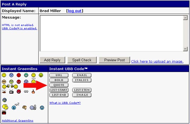
Posted by John Hawkinson (Member # 1135) on 06-08-2007, 03:53 PM:
I know, I don't like the way it looks ![[Frown]](frown.gif) Is it required?
Is it required?
--jhawk
Posted by Mark Gulbrandsen (Member # 72) on 06-08-2007, 07:36 PM:
Exactly what model IREM rectifier do you have. Older IREMS I believe have taps but the later ones have the movable core... The ones I am talking about are the early movable core type circa late 1970's.
And as far as building... them absolutely yes... I need 6 more of them and plan on building them in the shop for later installation. While the Neumade box is somewhat convenient it is pretty pricy. I was in the field when I needed these and construction of them on the booth rewind table is somewhat more time consuming as is parts procurement in a town with barely a Rat Shack.
Mark
Posted by John Hawkinson (Member # 1135) on 06-08-2007, 07:56 PM:
single-phase IREM P1-X80/C. Nameplate claims 220V input, and a laughable 85V no-load. But it's a Xetron nameplate, so I don't know what IREM rates it at...
I was curious if DIY switching boosters were popular. It seems there's some incidence of DIY high-reactance boosters...
--jhawk
Posted by Mark Gulbrandsen (Member # 72) on 06-08-2007, 09:57 PM:
This booster would work fine on yours. It works pretty much like the auto ignite relay on a lamphouse does. There is a zener and a relay. When the voltage drops below the zener firing voltage the relay drops out and kills the booster's power transformer. A 90 volt secondary tranny through a bridge rectifier would give you about 130 volts. Use about a 470uf cap on the output of the bridge for storage. Relay has a 48 volt coil and is in series with a 30 volt zener. A 150 amp stud mount diode blocks the boost DC voltage from the rectifier's DC. BE sure to heat sink and cool the diode adaquately. Be sure to adaquately bypass the stud mounted diode.
You might have a hard tme finding a 120/240 primary - 3 amp 90 volt secondary tranny... if you do EDCOR will custom wind one for you at a very reasonable price, probably around 50 bucks. I've used them for custom one up audio and power trannys before and their quality is first rate and delivery is really fast.
Mark
Posted by Louis Bornwasser (Member # 3063) on 06-09-2007, 08:56 AM:
Most of my rectifiers are IREM, 3 phase units; none have the booster. I have only filed one warranty claim in 15 years with Osram bulbs.(bad weld) Most 2kw bulbs are removed at 4500-5500 hours, still lighting perfectly and with clear quartz. (3500-4500 with 3kw bulbs) I never rotate; but I do super cool.
Voltage here is 207-210 volts.
FYI: That Italian rectifier was designed in Kentucky about 1963 by the late Frank Riffle when he wanted to import the CX-900 and x-400 lamphouses into the US on behalf of Carbons Inc; later Xetron/Neumade. Frank also designed the 6L6 along with RCA. Frank, was, at one time, the Altec/ERPI serviceman for Louisville, Ky and was the last president of Motiograph. Louis
Posted by Richard Fowler (Member # 893) on 06-09-2007, 10:45 AM:
The IREM models prior to the N series looked like circular trashcans ![[Smile]](smile.gif) We have installed boost kits on IREMS and Kneisley rectifiers for a client due to his voltage barely exceeding 190 VAC.
We have installed boost kits on IREMS and Kneisley rectifiers for a client due to his voltage barely exceeding 190 VAC.
Posted by Mark Gulbrandsen (Member # 72) on 06-09-2007, 11:36 AM:
The rectifiers I installed thses on are very early N series units. Probably late 70's vintage. Theaters that have a high leg are less suceptable to problems with these early units.
Mark
Posted by Dan Reiter (Member # 1386) on 06-11-2007, 02:18 PM:
On the IREM'S...
The input voltage is pre-wound at the factory. You cannot change it. 380 is for Europe, 220 for the States and Asia. Also, in agreement with the above, the older the IREM, the lower the open circuit voltage. With today's higher-pressure lamps, these older power supplies struggle to fire these newer lamps, especially as the lamps age. That is why you will find that if you say "BRAND X"'s bulb is no good and won't strike after a while, and then put in "BRAND Y"'s bulb, and VIOLA!!! It strikes, that is why. Best thing to do for the older IREM is to put in a full fresh set of diodes, replace the etlctrolytic caps, replace the RA board, and put in a fresh 230VAC contactor. Also, if your booth has a multiple tap feed transformer, kick it up. The IREM won't mind a little more on the front end. In extreme case, a booster unit, like the one noted above is the last hope before taking the plunge for a new power supply.
Very much like expecting your 1937 buick to operate like your 2007 BMW.
Posted by Michael Schaffer (Member # 1204) on 06-11-2007, 04:05 PM:
quote: Louis Bornwasser
I do super cool
We know that, Louis, with your pilot glasses in front of that plane. ![[Big Grin]](biggrin.gif)
Posted by Mark Gulbrandsen (Member # 72) on 06-11-2007, 06:42 PM:
We super cool too. Thats why we see 12,000 hours [lus out of Christie lamps.
quote: Dan Reiter
Best thing to do for the older IREM is to put in a full fresh set of diodes, replace the etlctrolytic caps, replace the RA board, and put in a fresh 230VAC contactor.
I did that before installing the boosters. Same 74 volt no load DC voltage. Shows how long lived the main capacitors in Irems are.
quote: Dan Reiter
Also, if your booth has a multiple tap feed transformer, kick it up. The IREM won't mind a little more on the front end.
Indeed the booths that these IREM's live in have multi tap trannnys feeding every 4 booths. But boy howdy, ya got to be careful there! If you kick up the main tranny then you risk the probability of everything else including the 120 volts going up and there are some pieces of gear that are not going to like that ![[Eek!]](eek.gif) . I disagree on kicking up the voltage. It is normally set once by the electrician or the power company during install. Now if your booth transformers feed JUST the rectifiers thats fine... I agree the IREMS can take it... in fact they're designed to. I just don't think you'll find the booth tranny feeding JUST the rectifier in most installs.
. I disagree on kicking up the voltage. It is normally set once by the electrician or the power company during install. Now if your booth transformers feed JUST the rectifiers thats fine... I agree the IREMS can take it... in fact they're designed to. I just don't think you'll find the booth tranny feeding JUST the rectifier in most installs.
I thik the booster angle is the best for rectifiers that can't make even 100 volts no load. I've priced out the components including custom wound power trannys and the cost is less then 120.00 for parts less labor per booster.
Mark
Posted by Michael Schaffer (Member # 1204) on 06-11-2007, 11:05 PM:
quote: Mark Gulbrandsen
We super cool too.
Sorry Mark, but you aren't cool. Certainly not as cool as Louis. That's nothing personal, I am just stating the obvious.
Speaking of the obvious, some lamphouse manufacturers warn about having *too much* air exhaust, and I wondered, why? Obviously, no one is going to cool the lamp down to freezing temperatures, so that shouldn't be an issue. Constantly repeated heating and cooling cycles could be, but since the air exhaust runs continuously, that wouldn't apply - the lamp would just heat up to a certain temperature and then level out.
Posted by John Hawkinson (Member # 1135) on 06-12-2007, 05:39 AM:
OK, it's time to OCR Osram's engineering document...*done*.
Let me email it to Brad...
Michael asks, "Why?"
Osram says, on p.25, "Excessive cooling is not good because it too can bring about increased arc instability due to turbulence in the lamp bulb. If the lamp voltage with cooling falls by more than 1 volt compared with uncooled operation, this normally means that cooling is excessive."
In some more detail, on p.32, they detail causes of arc instability, noting, "Bulb cooling: excessive forced bulb cooling increases the temperature gradient between arc and bulb wall, resulting in greater radial gas flow and turbulence which mainly affect the tail of the arc."
--jhawk
Posted by Mark Gulbrandsen (Member # 72) on 06-12-2007, 10:25 AM:
quote: Michael Schaffer
Obviously, no one is going to cool the lamp down to freezing temperatures, so that shouldn't be an issue.
Try the Teton Theater in Jackson Hole, or the Roman Theater in Red Lodge, MT. Both locations quite often go to more then 20 below which brings the booth temps during closed time to in the freeing range. Heat in the building comes up an ahour before opening but the booths take some time to gt that heat. neither location seems to be affected much by the cold... except for the projector oil.
Mark
Posted by Dan Reiter (Member # 1386) on 06-12-2007, 10:53 AM:
The most important aspect of lamp cooling is to not allow a major differential between the positive & negative ends of the lamp, a major differential between the ends and the seals, nor allow it to overheat. As well, the bulb does need to come up to an operating temperature so that all the gasses and internal parts heat up properly and "do thier thing". All manufacturers use different methods to cool the lamphouse and lamp itself. As long as the bulb does not discolor, it runs at normal specs, and there is no Anode or cathode damage, and the flame is steady & true, the lamp is running OK.
And, as we all know, cooler is better than hotter.
All said wearing my SQP work hat.
Posted by John Hawkinson (Member # 1135) on 06-28-2007, 09:52 PM:
Wow. Tonight I saw one of the scarier things I'd seen in a while. We were doing some lamphouse voltage measurements, and I needed my Fluke hooked up across the bulb terminals. So I ran two sheathed banana leads (you have to really try in order to make contact with them) out of the lamphouse, closed it up, and struck the bulb.
As the igniter pulse was going, the entire negative lead (a Fluke TL22) literally glowed (through the insulation). It was like there was a purple fluorescent light on inside the test lead. It was really quite something.
It certainly drives home why you should never have a digital meter hooked up when you strike the lamp (I didn't!)! I wish I'd been recording it on a camera...
--jhawk
Posted by Louis Bornwasser (Member # 3063) on 06-28-2007, 10:11 PM:
I am aware of the Osram statement about overcooling.
My experience is that overcooling is bunk; even though Osram says so. Louis
Posted by Brad Allen (Member # 470) on 06-30-2007, 03:13 PM:
I must add here, that sometime ago I was having problems with lamps (Osrams) igniting in my Kneisleys. With the advice of Mark G, Louis and Brad M. and others, I installed the Grainger/Dayton 550CFM blowers on top of each of the lamphouses. Each exhaust through it's own 10" flex duct to the outside.
Previously they had been exhausted with a single system that had been installed when the building was built, it was deteremined that it was only providing approx 100CFM of exhaust per lamp house.
All I can say is wow, it has made all the differance in igniting, stability of arc, and increased hours on the bulbs...just as everyone told me it would. Bulb envelope's are still good and clear even at 2500hrs and up.
I believe it might pass Louis's test of sucking up a shop rag. ![[Wink]](wink.gif)
Thanks Guys.
Powered by Infopop Corporation
UBB.classicTM
6.3.1.2