This is topic DFP-D3000 crosstalk problem on optical input in forum Film Handlers' Forum at Film-Tech Forum ARCHIVE.
To visit this topic, use this URL:
https://ft-forum.com/ft/cgi-bin/ubb/ultimatebb.cgi?ubb=get_topic;f=1;t=009927
Posted by Marin Zorica (Member # 1716) on 06-04-2009, 08:07 PM:
Hi!
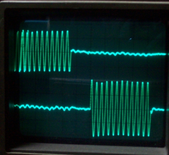
I'm bit confused here, have DFP-D3000, when trying to align best cross talk just can't get it good as usual, so I was mad, I did that million times and now problems....I hooked projector to another processor, also Sony but DCP-1000, normally I get picture on scope as this:
After that I just let projector run CAT97 and hooked cell cable and scope probes to DFP-D3000, but instead same, I get this on scope:
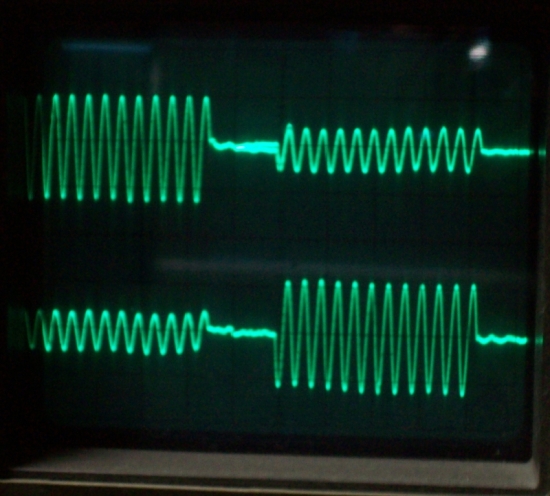
So obviously I have bad cross talk when using DFP, but why? As you can see on first is okay, and without touching cell or so connecting to this isn't same, I did use hadaphone connector on front panel as described in manual, but I also try TP102/103 on APR34 board which are direct preamp outputs from projector 1 optical input.
I look wiring 1000X times, all acording to manuals, also when I set sound head and calibrate level and HF on DFP processor do sound good, but this cross talk issue just killing me, I hope someone here will know more.
Posted by Stan Gunn (Member # 554) on 06-05-2009, 09:53 AM:
The first waveform is perfect, the second shows me that the cell is to far from the cell.
But there may not be excesive cross talk, just move cell closer
to the film.
Stan Gunn. ![[Smile]](smile.gif)
Posted by Demetris Thoupis (Member # 833) on 06-05-2009, 10:40 AM:
Stan did you actually read his post? He says that the first readout is without the processor connected and the second is with the processor. Is not a matter of alingment is a glitch in the famous wonderful magnificent SONY piece of crap!
Posted by Marin Zorica (Member # 1716) on 06-05-2009, 05:19 PM:
quote:
Stan did you actually read his post? He says that the first readout is without the processor connected and the second is with the processor. Is not a matter of alingment is a glitch in the famous wonderful magnificent SONY piece of crap!
Firs scope is with DCP1000 processor, so cell aligned properly as we can see, other is same soundhead, but with DFP-D3000 processor, only don't know why crosstalk apperas.
Posted by Kenneth Wuepper (Member # 1174) on 06-05-2009, 05:25 PM:
Marin,
I have seen this before. If the common wire to the cells becomes disconnected, they are then in series and it appears as if there is crosstalk. Look for a missing common conductor connection in the input from the cells to the processor .
KEN
Posted by Marin Zorica (Member # 1716) on 06-05-2009, 05:59 PM:
Thanks Ken, that makes perfectly sense, but I think is same on both projector inputs....so doubt that something gone bad on both....but I will check!
Posted by Kenneth Wuepper (Member # 1174) on 06-05-2009, 08:16 PM:
Marin,
If the signal is proper at the cells, where did you connect the scope to get that reading?
The signal is bad on more than one processor so that eliminates the processors. You tried the cells on more than one input so that eliminates the pre-amps.
Then the problem is between the cells and the processor inputs.
The connections from the cells to the cable at the sound head end, a bad cable or the connections from the cable to the processor input are bad.
Could the common wire be to the WRONG pin in the processor input connector?
KEN
Posted by Marin Zorica (Member # 1716) on 06-06-2009, 04:41 AM:
On first picture where signal is okay scope is connected to SONY DCP1000 processor Lt Rt test points and all is okay, but when I connect same cell, same projector without anything touched...so sound head is fine to DFP processor I got signal with crosstalk like on second picture, I tried to recheck pinout many times but still the same....
I use two balanced shielded cables from cell to processor:
Cell red wire connected to L cable HOT
Cell green wire connected to R cable HOT
Cell black connected to COLD of both cables
Ground isn't connected on cell end.
L cable goes to processor L input HOT, COLD and GND
R cable goes to processor L input HOT, COLD and GND
When DCP is connected in that way signal is okay, When DFP is connected crosstalk apperas.
When I connect only one channel to input there is not crosstalk on other channel, so problem isn't either is processor......
I'm feeling stupid here really....because when R+ R- GND L+ L- is connected to input of other processor is okay, same terminals connected to DFP bad....
Posted by Steve Guttag (Member # 268) on 06-06-2009, 06:52 AM:
You do have the headphone rotary switch in the correct position, don't you? When you rotate it, the display will show what is supposed to be coming out (Lt/Rt is what you want).
Steve
Posted by Marin Zorica (Member # 1716) on 06-06-2009, 07:23 AM:
I know, it should be on position 1 when doing A-cain. Bu I even connected directly to preamp output and is same as on hadaphone output.....
Posted by Darryl Spicer (Member # 711) on 06-06-2009, 11:19 AM:
Could it be a glitch in the DFP-D3000. Meaning the cell is lined up correctly because you are getting a good reading on the DCP-1000 but a bad reading on the other unit. What does a movie sound like when you play it. Do you here a lot of cross talk in the surrounds? The glitch might be at the test points of the DFP-D3000 but the unit may be playing the sound correctly. That's just my thoughts. I am not that familiar with these units.
Posted by Marin Zorica (Member # 1716) on 06-08-2009, 01:37 PM:
No!
Because when I connect only oen channel there is no signal on other. If there was crosstalk in processor than it will be there too with other channel disconnected.
I did researched a bit more, I tough maybe is some bad lead from back panel connector to APR34 board and I did found something unusual...that input stage in manual (schematic) isn't same as it on this board....don't know why but sure isn't, maybe it was some revision? On manual says units with serial 10001 an higher, mine is 10334....so it should be same?
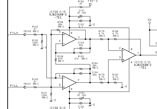
....there we can see that P1LH (pin2 on input dsub) is going to pin 5
of IC106, and P1LL (pin 6 on input dsub) is going to pin 5 of IC106.....but
NO!
I've found different here, P1LH is going to pin6 of IC106, but P1LL is going
to pin3 of IC106, and also pin3 and 5 are not connected together like on
schematic, don't know why, but something is probably wrong here and HOT or
COLD inputs are bad???
Posted by Tony Bandiera Jr (Member # 2365) on 06-08-2009, 06:07 PM:
The real problem is that it's a Sony.
Sounds like form the last post that perhaps Sony didn't correctly wire the APR34 to backplane interface.
Posted by Gordon McLeod (Member # 33) on 06-08-2009, 10:45 PM:
I think they are using it as a hi common mode rejection circuit to create the balanced input
the common of the cell is probably the problem
Posted by John Hawkinson (Member # 1135) on 06-09-2009, 12:04 AM:
Marin, I think you might be reaching a false conclusion. When you say, "If there was crosstalk in processor than it will be there too with other channel disconnected."
I don't think that's necessarily true. This is what we call "analog weird shit." If your signal is grounded, or it is floating, you might not see the same crosstalk you would see if you have the impedence effects of the long cable run. Or even antenna effects....
It depends on how much the processor decouples the test points from the input signal. And I would bet here, "not very much."
--jhawk
Posted by Scott Christopher (Member # 834) on 06-09-2009, 12:40 AM:
So you're saying both 'hot' and 'cold' inputs are going to the same pin on the same IC (non inverting input)? Wouldn't this cancel the input signal if tied together?????
I've always known it to be one input to the non-inverting input and the other to the inverting input.
Check you're board again. Is it wired the same for Right?
I just noticed the waveform is inverted between your two images (different processors) This may be a clue
Posted by Marin Zorica (Member # 1716) on 06-09-2009, 01:30 PM:
quote: Scott Christopher
So you're saying both 'hot' and 'cold' inputs are going to the same pin on the same IC (non inverting input)? Wouldn't this cancel the input signal if tied together?????
NO, both are going to non inverting inputs, but each on each OP, this OP is dual.
quote: Gordon McLeod
I think they are using it as a hi common mode rejection circuit to create the balanced input
the common of the cell is probably the problem
Probably I think it's "problem", but where to find cell without common, I hear, but newer saw one?
Did anyone install this processor with regular solar cell??
Posted by Gordon McLeod (Member # 33) on 06-09-2009, 02:07 PM:
Are you using 2 2conductor cables from the cell to the processor or a 4 conductor or a 3 conductor
On the 9pin d sub the common on the cell must be connected to both pin 6 and pin 9 so for a standard solar cell the red wire goes to pin 4 green goes to pin 5 and the black to pin 6 and 9 and the shield to 1 and 4
Posted by Kenneth Wuepper (Member # 1174) on 06-09-2009, 02:56 PM:
Gordon,
Check your last post. It seems you have an error in the pin numbers.
KEN
Posted by Gordon McLeod (Member # 33) on 06-09-2009, 04:22 PM:
Red 2
green 5
black 6 and 9
shield 1 and 4
seems one can't edit a post after a certain time frame
Posted by Marin Zorica (Member # 1716) on 06-09-2009, 04:29 PM:
quote: Gordon McLeod
Red 2
green 5
black 6 and 9
shield 1 and 4
Yap!
Just like that, I'm using two wired shielded cable (2 wires shield) one per channel.
Posted by Scott Christopher (Member # 834) on 06-09-2009, 07:46 PM:
quote: Marin Zorica
both are going to non inverting inputs, but each on each OP, this OP is dual
but earlier you wrote quote: Marin Zorica
P1LH (pin2 on input dsub) is going to pin 5 of IC106, and P1LL (pin 6 on input dsub) is going to pin 5 of IC106
To me, that's one IC - You've decribed both inputs going to the same pin (pin 5 on IC106).
On a dual Op-Amp, there's only ever been one pin 5..... Therefore is this an error in you post? If both inputs are tied to Pin 5 on the same IC, I'm pretty sure that would cause a problem.
Posted by Marin Zorica (Member # 1716) on 06-10-2009, 05:04 AM:
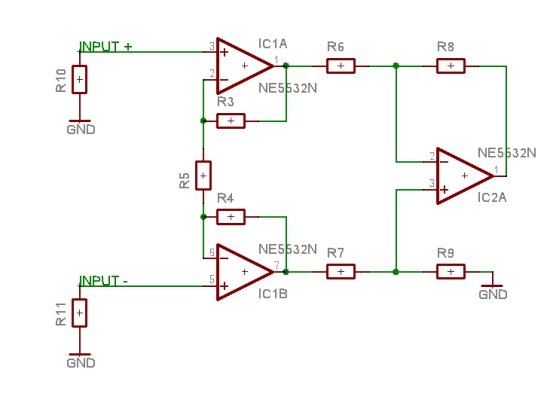
Sorry Scott, I did write wrong, one is going to pin5 and other to pin3 of same IC (so both are going to no invert inputs.
So, I think input now looks like this:
Posted by Gordon McLeod (Member # 33) on 06-10-2009, 07:18 AM:
that is a classic balanced input stage
Posted by Scott Christopher (Member # 834) on 06-10-2009, 08:26 AM:
quote: Marin Zorica
When I connect only one channel to input there is not crosstalk on other channel, so problem isn't either is processor
I originally thought you may be getting a small L+R mix, but not according to your tests.
Have you tried plugging it into another projector (a known good setup)?
Posted by Marin Zorica (Member # 1716) on 06-10-2009, 10:01 AM:
Yes I did, this one is good also, other one is too....but same on other.....
I know this is balanced input, nothing strange....but it looks like common wire is missing, but it isn't.....
Posted by Gordon McLeod (Member # 33) on 06-10-2009, 10:12 AM:
Many newer processors have a jumper for cell vs reverse scan readers mainly because a solar cell is not a true balanced device since the two - leads are common on a cell where as a reverse scan with the internal preamp has two balanced outputs
Posted by Marin Zorica (Member # 1716) on 06-10-2009, 10:56 AM:
I know that, but I newer saw cell without common COLD, even I know they excist. Didn't find anything in manual about cell/rev scan reader....also, in schematic there is no jumper as is no on board....
Posted by Gordon McLeod (Member # 33) on 06-10-2009, 11:01 AM:
You may have to get two small shield 600:600 ohm transformers to isolate the common of the cell from the two inputsof the processor
Posted by Marin Zorica (Member # 1716) on 06-10-2009, 11:08 AM:
That's what I tough on also, but better is to make some preamp than to deal with bad transformers....or to steal them from some CP50
Posted by Sam D. Chavez (Member # 1841) on 06-10-2009, 04:11 PM:
It is possible the cell itself has a problem with the common becoming compromised. Cells do fail at times. Everything will look more or less normal, but when you play film you will not get a surround signal as the stereo cell will essentially turn into a mono cell.
Posted by Marin Zorica (Member # 1716) on 06-10-2009, 06:22 PM:
Yea, true, it can sometimes go "bad". BUT, I did try on three different machines I have around me now, all do have aligned readers and 100% working good.
Posted by Sam D. Chavez (Member # 1841) on 06-11-2009, 02:27 AM:
Are we talking cells connected directly to processors or readers connected to the processors?
Posted by Marin Zorica (Member # 1716) on 06-11-2009, 06:01 AM:
Cells.
Posted by Alan Haigh (Member # 1781) on 06-20-2009, 10:02 AM:
So the cell has a single common (or negative) rather than one for left and one for right. - I think for this balanced input you'll have to connect pins 6&9 to 1&4 colds to ground, - otherwise you are putting the left and right cold into the cold of both. -- I think it must be an impedance thing - the transformers would be the best solution - near the projector. I believe Sony did redesign this input circuit to work with solar cell impedances, which are incredibly low.
Posted by Marin Zorica (Member # 1716) on 06-20-2009, 11:53 AM:
Well.....it work when I connect cell common to audio GND, hot to hot of input and shield of cable to chassis, like on Dolby.
But maybe they had other revision of this board....even on manual is different (better) preamp, but my board has different, on manual it says unit with serial 10001 and higher...mine is 10334.....
Powered by Infopop Corporation
UBB.classicTM
6.3.1.2