This is topic Repairing DTS XD-10 Mother Boards (Do Not try This At Home!) in forum Film Handlers' Forum at Film-Tech Forum ARCHIVE.
To visit this topic, use this URL:
https://ft-forum.com/ft/cgi-bin/ubb/ultimatebb.cgi?ubb=get_topic;f=1;t=010701
Posted by Mark Gulbrandsen (Member # 72) on 11-15-2010, 03:39 PM:
Recently I had a number of XD-10's that upon power up would just sit in "Initialize". Subbing in modules from another working unit is the quickest way to trouble shoot one of these so I proceeded to do so but to no avail. Then while subbing in a new power supply I noticed that several of the electrolytic capacitors on the motherboard had bulging tops on them. The CPU was also cold even without the fan attached to it's heat sink... so it quickly became apparent that the on board regulators for the CPU had been killed by failing electrolytic capacitors. The typical cost to have this repaired/upgraded to a new motherboard by DTS is $1200 USD plus. There are also places that can repair mother boards... the cost ranges from 75USD on up... But in this case I thought... Hey, I am good at board level work so why not try replacing them myself. Well, I did and I have since rebuilt three of these (A-Open) boards and saved my customer a ton of $$$$. These XD-10's are only going to have to run a couple more years at best before conversion so spending over 1200 USD per unit was pretty hard to justify.
Again... DO NOT TRY THIS AT HOME! You need the proper desoldering equipment, at least the 32 years of electronic experience I happen to keep in my back pocket, new capacitors of the same value, and much care and finese to accomplish this without damaging the board... Some of the traces are hair fine. One thing you DO NOT NEED is good spelling ability ![[Roll Eyes]](rolleyes.gif) !
!
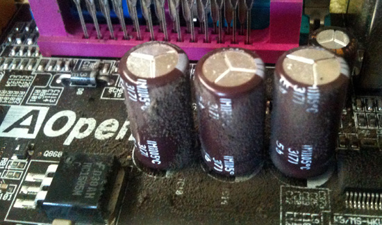
The cap in the center is normal compared to the top on the other two. I checked the caps value after I removed them. None had shorted... all had gone way way down in value.
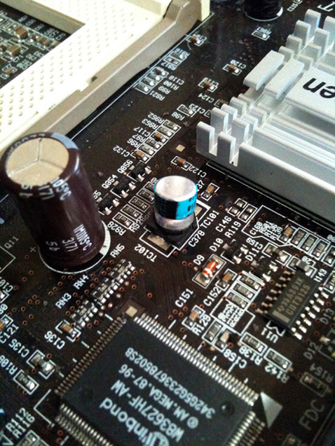
The blue capacitor in the center was blown half way off it's base. This is an SMT capacitor and I could not obtain it locally so I soldered in a Tantlum cap of the same value.
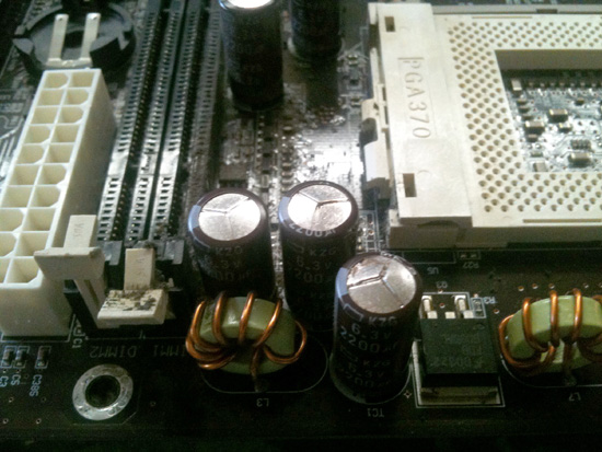
More bulging tops. In all I replkaced 10 electrolytic caps all located in and around the CPU and chip set. I left the other electrolytic caps in place as they were different values and brands. None of the others had bulging top syndrome.
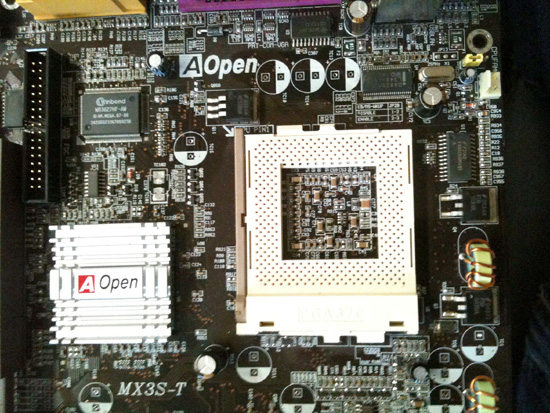
Old caps removed and most of the holes de-soldered. New caps go in fast once the old ones are out.
Posted by Steve Guttag (Member # 268) on 11-15-2010, 04:15 PM:
Great post!
Posted by John Hawkinson (Member # 1135) on 11-15-2010, 06:15 PM:
Are these lead-free solder? I replaced the caps on a 17" apple iMac motherboard and needed to heat the board with two soldering irons, one from each side (yes, we used flux!) to get the solder to flow. We theorized this was because of the higher temperature requirements of lead-free solder, but it was a huge pain.
I had thought we were finally done with "capacitor plague" issues, but maybe not.
--jhawk
Posted by Monte L Fullmer (Member # 2797) on 11-15-2010, 08:05 PM:
..prob best to use a variable watt soldering station with a fine pencil tip iron to do all of this cap and momboard rebuildings..
Speaking of which I need to rebuild an automotive ECU with the same cap problem of being swollen and leaking.
Posted by Ron Lacheur (Member # 1126) on 11-15-2010, 08:13 PM:
Electric de-solder tool like a Hakko 808 works wonders on repairs like this.
Posted by Mark Gulbrandsen (Member # 72) on 11-15-2010, 10:03 PM:
Thanks Steve...
@ Ron...
I use an old Weller DS600 that I bought on Ebay some time back to do QSC rebuilds. There are several points that do require a slightly larger and hotter iron and I just carefully use some solder wick at those points... which seem to be on or connected to the ground plane. I'm guessing this is at least a four layer board. I do not believe it is lead free. I looked up the date and the manual of the motherboard on the internet and it is ~ 2003. There are some of these boards on Ebay right now for 25.00 but I donno if the caps have been changed out or not or if they will fail. Changing these out is about a 2 hour project if you take your time. Of course you first have to dismantle the XD-10 to get the board out. Remove the back up battery, all memory, and the CPU when working on the board. It's highly likely the CPU heatsink will need a serious cleaning anyways. The thre that I have done had heat sinks that were at least 80% plugged up.
The caps that are failing are 2200 mfd @ 6.3 vdc. I used 2200 mfd @ 10 volt... they were the same physical size. The small blue cap is either a 47 or 4.7 @ 6.3 volts... I honestly can't remember. but a tantlum cap of the same value and voltage is easier to deal with than the tiny SMT cap that was there.
Mark
Posted by Ron Lacheur (Member # 1126) on 11-16-2010, 12:22 PM:
Most of the PCB's I've worked on, the Hakko has worked wonders. The Weller unit looks pretty awesome though!
I'm surprised that DTS didn't put in a ASUS motherboard.
Posted by Mark Gulbrandsen (Member # 72) on 11-16-2010, 06:34 PM:
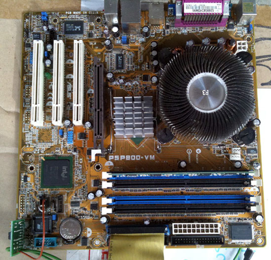
They did use Asus... in later versions. The little piggy back board at lower left is to turn the board on and off via the fornt panel switch. Older units had crimp ons across the green and black power supply control leads going to the front panel power switch to turn on and off. Have not had any problems with these baords except the heat sink fins getting clogged like this one. The A-Open board uses the same heat sink. Both sport a celery on proceessor. Just for kicks I stuck a Pentium in place of the Celeryon and it speed up boot time by 50%. Of course you are not going to see or hear any difference in audio playback.
Mark
Powered by Infopop Corporation
UBB.classicTM
6.3.1.2