This is topic CP65, DA 20 and remote with LED wiring in forum Film Handlers' Forum at Film-Tech Forum ARCHIVE.
To visit this topic, use this URL:
https://ft-forum.com/ft/cgi-bin/ubb/ultimatebb.cgi?ubb=get_topic;f=1;t=011388
Posted by Bernie Anderson Jr (Member # 410) on 02-04-2013, 12:32 AM:
Hi guys,
I'm running my CP65 with a DA 20. Per the manual the control wires are hooked up using J6 on the DA 20 to J18 on the CP65. I want to add a remote with LEDs for the screening room. I can do the easy way out and just connect to the automation contacts on TB1, but I rather have the LED indicators for the current format.
How should I wire both the DA20 and the remote with LEDs to the CP65?
Thanks
Bernie
Posted by Carl Martin (Member # 1146) on 02-05-2013, 05:57 PM:
i built a cp65 remote last year. you simply connect the leds between the IDx pin for each format and pin 13 (+15). no additional resistors needed. connecting the da20 at the same time is not a problem, other than (in my case anyways) it caused the mono led to glow slightly even when that format was not selected. i have no idea why that was.
Posted by Bernie Anderson Jr (Member # 410) on 02-05-2013, 11:40 PM:
Thanks Carl,
Could you send me pictures of your remote box? I want to see how yours came out.
How did you physically connect the DA20 and the remote? Breakout board?
Thanks
Bernie
Posted by Markus Ito (Member # 6207) on 02-06-2013, 12:44 AM:
Are you using this to switch formats on the CP-65? I have a CP-55 paired with a DA20 and have two remote boxes I use to switch the format (one at each projector). The wires are running back to a board which is screwed to the backplane of the CP55. I believe this board came with the processor. The remotes are simple breakout boards with momentary switches for each format switch (essentially duplicating the switches on the CP55) and a led in each switch to indicate if the format is active. I'm not sure how much of this applies to the CP65, but I believe that the automation connector has the same pinout, so you should be able to do something similar.
Markus
Posted by Carl Martin (Member # 1146) on 02-06-2013, 04:38 AM:
bernie,
as far as i know, my remote box is still attached to the wall in the booth at my former theater, now digital. i hope to salvage it for my own use at some point.
the primary reason i built it was to allow the automation to mute/unmute or select local/remote faders (to automatically increase volume at feature start per brad's tip) regardless of what state the processor was in already, so it would self-correct if it ever got into the wrong state, which sometimes happened in special circumstances. i included format selection buttons and indicators while i was at it since the sound rack was in the other end of the booth.
i replaced the ribbon cable between the cp65 and da20 with a longer one that had 2 female connectors, and ran a 25 ft cable between the extra female and my box. perhaps there are better ways of doing it.
Posted by Carsten Kurz (Member # 5396) on 02-06-2013, 06:48 AM:
The only thing to think about is how to use the ID out signals for both DA20 AND LED display. You can use the TB1 pins for the actual button interface, very easy.
What kind of DB25 cable is connected between your CP65 and DA20? DIY, round cable, flat cable?
edit: From the DA20 installation manual, I just notice that CP65 ID lines are not connected to DA20 anyway. So, no problem, you just need a way to tap into the automation connector for the LEDs. How easy that will be depends on the cable you use. A ribbon cable with IDC DB25 connectors would probably be the easiest way to do it.
As for buttons, there are nice classic style 'ITT SCHADOW digitast' momentay switches with built-in LEDs. The switch type is the same as Dolby used them on the CP65 front panel. Should be available at the usual electronic parts suppliers like DigiKey.
- Carsten
Posted by Bernie Anderson Jr (Member # 410) on 02-06-2013, 04:50 PM:
Carl,
I'm using a flat ribbon cable from the DA20 to the CP65.
Is it as easy as getting a DB25 Y splitter, plugging the one end into the CP65, then the split between the DA20 and the remote boxes? If you run multiple remote boxes, say at both projectors, the contacts are just in Parallel?
Posted by Carsten Kurz (Member # 5396) on 02-06-2013, 05:10 PM:
If you have a ribbon cable, you can simply add another IDC connector anywhere in the cable and attach the remote box to it. Yes, you can wire switches in parallel. I would still use TB1 for the buttons and the ID lines for LEDs.
- Carsten
Posted by Bernie Anderson Jr (Member # 410) on 02-06-2013, 06:40 PM:
I get it. I didn't think about that with the ribbon cable.
What's your resoning for staying away from wiring everything at that one connector? It makes it alot easier that way.
Thanks
Bernie
Posted by Carsten Kurz (Member # 5396) on 02-07-2013, 12:43 PM:
I just wouldn't interfere with the existing connection and signaling between the DA20 and CP65. The CP65 will know the best way to deal with simultaneous signaling on the automation connector and TB1.
If there is an unused connector like TB1 - why not use that? It's not really more wiring effort, you can also tap into the DB25 from there.
Also, any failures on the remote box wiring, during plugging, etc. could cause the CP65->DA20 communication to fail completely. I simply would consider the TB1 option the safer way.
- Carsten
Posted by Tony Bandiera Jr (Member # 2365) on 02-07-2013, 01:12 PM:
Bernie:
The easy way to do this is to use one of these:
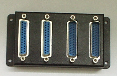
It is simply a series of four parallel DB25 connectors, I have used them many times for both control and audio and they work great. They can be found at Fry's or other electronic dealers. If you can't find one, PM me as I may have a spare or can buy one for you locally and send it to you. They are about $15.
And if you want me to build you a remote PM me on that.
quote: Carsten Kurz
I just wouldn't interfere with the existing connection and signaling between the DA20 and CP65. The CP65 will know the best way to deal with simultaneous signaling on the automation connector and TB1.
If there is an unused connector like TB1 - why not use that? It's not really more wiring effort, you can also tap into the DB25 from there.
Also, any failures on the remote box wiring, during plugging, etc. could cause the CP65->DA20 communication to fail completely. I simply would consider the TB1 option the safer way.
Sorry Carsten, there are so many flaws with your thinking on that. ![[Big Grin]](biggrin.gif)
First off, the TB1 and DB 25 connections are electrically the same and the CP-65 does not know or care which one gives the signals. You can use a meter between TB1 and the same ID'd pins on the DB25 and see that they are hardwired together.
Second, using the DB25 in parallel will NOT interfere with the logic signalling between the DA20 and CP65. (Remember that the TB1 is electrically the same so it makes no difference.) And the signals are very simple logic highs and lows (contact closures really) so there isn't "communication" in the sense that say serial data would be.
Third, in the event you DO have a problem with your remote control is is a lot easier and faster to unplug a single DB25 than to unscrew a bunch of screws on a fanning strip.
Fourth, soldering and installing a fanning strip is more effort than using a DB25.
Now, all that said, if you happen to be using one of the CAT410 Logic ("pulse stretcher") connectors on the DA-20 to CP-65 control lines, it needs to go on the cable FROM the DA-20 into the multi block I posted above, NOT between the multi block and the CP-65. (In other words, you don't want the CAT 410 to be between the CP-65 and your remote, just between the DA-20 and the CP-65.)
Posted by Bernie Anderson Jr (Member # 410) on 02-08-2013, 01:57 PM:
Tony, I PM'd you.
Thanks
Bernie
Powered by Infopop Corporation
UBB.classicTM
6.3.1.2