This is topic Christie ignitor failure - where to start? in forum Film Handlers' Forum at Film-Tech Forum ARCHIVE.
To visit this topic, use this URL:
https://ft-forum.com/ft/cgi-bin/ubb/ultimatebb.cgi?ubb=get_topic;f=1;t=011477
Posted by Craig Huegen (Member # 7666) on 06-17-2013, 10:07 PM:
I have a Christie CH10 lamphouse (part of that hobby implementation I spoke of) that has an IGA10M ignitor in it, which will no longer strike.
We have 120V to the lamphouse, but no buzz with manual strike button and no autostrike. I can see a tiny flash / arc inside the manual strike switch itself when I push the button, so I can see there is power to the ignitor.
Just minutes earlier, it struck fine.
Before I take things apart, I'm here to collect ideas on what is likely wrong and any tips. From what I read here and in other places, my educated guess is the relay or HV transformer.
As I understand it, the relay case is clear so I can see whether it's pulling properly when the button is pushed -- if the relay appears to work, suspect the HV transformer.
Sound about right? Any other places you'd look, given those symptoms?
Posted by Sean McKinnon (Member # 612) on 06-18-2013, 08:54 AM:
I am not clear on what you mean by...
quote: Craig Huegen
I can see a tiny flash / arc inside the manual strike switch itself
Does that mean you can see the switch arcing across its contacts or you can see into the lamphouse through the opening for the switch and you see arcing inside the lamphouse?
If the latter you could have a grounding situation in the lamphouse or you are not building up enough no load (open circuit) voltage and are seeing a spark across the lamp but there is not enough to establish the arc.
Posted by Dave Macaulay (Member # 813) on 06-18-2013, 10:29 AM:
First of all you have to be very fricking careful. 120V line power can kill you but generally just gives you a jolt to remind you not to touch it. The ignitor HV is more likely to just kill you.
Checking the HV transformer with an ohmmeter is the first step (no AC power connected!), the primary should be fairly low resistance - under 100 ohms probably, and the HV side should be fairly high - 10K at least as a guess? Neither side should have any continuity to ground.
The Christie ignitors are a bit different than others, they use a delay device to limit strike time to avoid burning out the HV transformer. This delay device can fail, that either disables the ignitor or disables the protection.
Check the delay device. The contact layout should be printed on its case, check for continuity between the power and load terminals.
Testing this delay under power is a bit risky - I do not like to have meter probes on things in there if the HV can potentially turn on. Disconnect one HV transformer primary wire and check for line voltage on the transformer's supply terminals (where you disconnected it from) with the ignitor powered and activated.
The spark gap is pretty foolproof but may be a problem. You can clean the spark gap contacts I think, note the electrode spacing and get it back the same when done if you disassemble it. The capacitor is pretty much indestructible.
You can test the HV transformer if you have a variac supply. If you connect the line side to the variac output and meter the HV output, applying a volt or three on the input will give a measurable but not destructive output voltage. Any normal voltmeter will be destroyed if you try to measure the output at full line voltage input, you would need a special set of HV probes.
It's possible for the transformer to arc internally at operating voltage but seem fine at lower voltage, so the variac test doesn't prove the transformer is OK.
If you find and fix a problem and want to test the complete ignitor: you must provide a reasonable spark gap at the output studs. Without an external arc path the arc will be somewhere inside the unit, and probably damage something. Use wire stiff enough to hold its shape, I use 14ga solid wire from whatever old electrical cable is lying around or coat hanger wire. Wrap a length around each of the studs and secure with the nuts. bend the wires so the ends point together about 1/2 inch apart, when testing you should see a bright hot spark arcing between them.
If the delay device is working, the ignitor will shut itself off after a second or two of arcing, then come back on for a second or so every 5 or 10 seconds.
Don't be too close to the unit under test.
Posted by Craig Huegen (Member # 7666) on 06-18-2013, 01:58 PM:
quote: Sean McKinnon
Does that mean you can see the switch arcing across its contacts or you can see into the lamphouse through the opening for the switch and you see arcing inside the lamphouse?
The former. As the switch contacts close you can see a small arc, meaning there is power to the circuit at least.
...and to Dave, thank you for the tips. I am familiar with high-voltage sources and flybacks, so I do my best to avoid them. I'll see what I can find out.
Posted by John Eickhof (Member # 323) on 06-18-2013, 04:25 PM:
Take a DC voltmeter and check the voltage across the DC leads from the power supply (Located at the back of the lamphouse behind the cover with the lamp info cardholder) What is probably occurring is that there is over 90-95 open circuit volts at that point. C & CH series igniters will only make one attempt to strike automatically until the open circuit voltage goes below 70 v or so, the manual strike button is bpassed by the time delay relay in the igniter until the voltage drops, this is how christie kept the igniter from trying to strike once the lamp was lit. Yes its a pain in the arse! The only way to eliminate this is to rewire the igniter so the manual button supplies 120v to the appropriate terminals on the igniter and the time delay relay is byspassed. I would leave this task to a qualified technician. The only other remedy is to let the unit sit untill the DC voltage drops. Then it will try to strike again. Good luck
Posted by Craig Huegen (Member # 7666) on 06-18-2013, 07:15 PM:
It's not an open voltage too high problem, as I've turned off the rectifier and no power is present at the DC terminals. Generally, hitting the manual strike button will at least create a buzz at this point, but it doesn't.
I pulled the side of the ignitor and can't see anything obvious... the clear relay does not pull in when I push the button, so would that point to the time delay relay being broken/stuck closed?
Posted by Louis Bornwasser (Member # 3063) on 06-18-2013, 08:05 PM:
Two thoughts: The "emergency strike" is hot wired direct, I think. Also there are only 3 wires to the hv transformer: 2 are AC in and the other is hv out. The hv other wire is grounded to the frame of the transformer. Louis
Posted by Craig Huegen (Member # 7666) on 06-18-2013, 09:25 PM:
quote: Louis
Two thoughts: The "emergency strike" is hot wired direct, I think. Also there are only 3 wires to the hv transformer: 2 are AC in and the other is hv out. The hv other wire is grounded to the frame of the transformer. Louis
If the emergency strike bypasses everything (I haven't probed a lot at the terminals, just physically inspected things so far) then I do have a more serious problem it seems.
The resistance on the secondary HV tab to the frame of the tranformer is showing infinity - so I'm thinking the secondary has burned through on the transformer?
Posted by Monte L Fullmer (Member # 2797) on 06-18-2013, 10:54 PM:
That IGA10M igniter uses that glass "heater tube" delay relay to break the current to discharge the capacitor for the coil.
Seen that "heater tube" fail which fails to autostrike the bulb when power is supplied and one has to use the manual ignition button on the console - that is hooked up in parallel with the tube.
It's an Amperite tube (forget the model number, but a 7 pin minature tube) that has a heater coil inside and contacts. The coil heats up to make a thermal strip inside with a contact on top bend to break contact to discharge. Could be the heater section of this tube has gone out.
Even the SLC and SLC-45 Consoles that used the IGA15M igniters, their Amerite delay-relay units loved to fail. I used to carry a bunch of these units to replace at my theatres.
Posted by Craig Huegen (Member # 7666) on 06-19-2013, 12:25 AM:
Thank you for the suggestion, Monte - however in this case, even the manual "emergency start" button is not striking the bulb (no hiss/buzz when you hit it).
Posted by Monte L Fullmer (Member # 2797) on 06-19-2013, 03:00 AM:
Sorry, a nine pin miniature tube variety .. being the G Series TDR from Amperite. Doesn't take much to break a wire in the heater winding to disable contact function in the tube itself.
Pull the tube and do a continuity check between pins for the heater section.
Tried a different bulb? and hope it's not an Osram, for they are terrible in a CH-10 console.
Posted by Craig Huegen (Member # 7666) on 06-19-2013, 11:09 AM:
(First, I need to correct my original post -- I have an H10 lamp house, not a CH10 console... sorry about that stupid mistake!)
I did try another bulb with the same results -- you can't hear the ignitor buzz at all.
From your past post, I thought I understood the emergency strike button bypasses the time delay and tube and sends line voltage to the HV transformer to arc the bulb, yes? That (in combination with infinite resistance through the HV secondary) would lead me to suspect the HV transformer failed, as from there it's just a matter of a wire that connects to the positive bulb electrode through the "snout" of the ignitor.
I don't believe I have one of the delay tubes referenced here - my ignitor is dated 2007, labeled "Christie IGA-10M REPAIRED" and there appears to be one of the black plastic time-delay relays at the bottom (when facing the ignitor as mounted in the lamp head).
Am I headed in the right direction?
Posted by Louis Bornwasser (Member # 3063) on 06-19-2013, 03:28 PM:
The glass tubes were discontinued; The plastic time delay relay is a direct replacement. I have never seen either to fail much. I think the dicontinuity in the transformer primary is your problem.
H10 and CH 10 are identical except for the case. Louis
Posted by Craig Huegen (Member # 7666) on 06-19-2013, 07:25 PM:
Any idea as to the transformer winding ratio in case I seek another?
I'll look for another used ignitor module too.
EDIT: Here's the goodies picture:
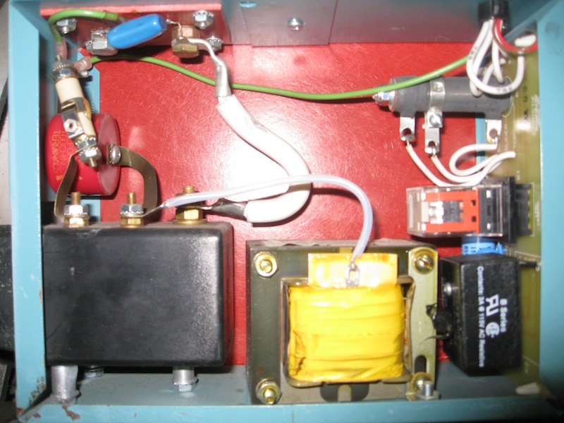
Everything looks relatively healthy, with only minor burns on the metal strip surrounding the white insulator on the left. There is infinite resistance between the HV terminal in the center of that transformer and ground.
Posted by Monte L Fullmer (Member # 2797) on 06-19-2013, 10:59 PM:
On the delay/relay unit to the lower right: is the top of the unit swollen by heat of any kind?
Not to carry a tune forever, but have seen 15M's with dead 'black boxes' only being in service for a couple of years..
Posted by Craig Huegen (Member # 7666) on 06-20-2013, 11:47 AM:
It doesn't appear so, Monte; the same question still exists, though -- doesn't the "emergency strike" button bypass all of that stuff and send 120V to the HV transformer primary anyway?
I ask the question simply because I haven't traced it out to determine whether the emergency strike button feeds voltage into the relay and time-delay circuit, or whether it bypasses all of it and just fires the pulse.
Posted by Craig Huegen (Member # 7666) on 06-20-2013, 11:42 PM:
EDIT: found the schematic. The emergency button bypasses everything. Further inspection of the HV transformer indicates windings are burned through. I'm off to find a new transformer / ignitor I suppose!
Powered by Infopop Corporation
UBB.classicTM
6.3.1.2