This is topic Allanson Power Supply in forum Film Handlers' Forum at Film-Tech Forum ARCHIVE.
To visit this topic, use this URL:
https://ft-forum.com/ft/cgi-bin/ubb/ultimatebb.cgi?ubb=get_topic;f=1;t=011582
Posted by Bill Yacey (Member # 6102) on 01-01-2014, 05:07 PM:
I'm looking for schematics for an Allanson General Sound Xenon power supply, Cat. #1233-1.
It's a 2KW supply, 208V 3 phase unit. If anyone has any info or experience with these units, I would appreciate hearing from you.
Thanks
Posted by Gordon McLeod (Member # 33) on 01-01-2014, 10:30 PM:
I believe we have a schematic for it somewhere it is a copy of the Sanrex rectifiers made for the Xebex supersol
it is a large print and will not scan easily
Posted by Bill Yacey (Member # 6102) on 01-02-2014, 12:05 AM:
It was coupled up to a Strong Super Lumex lamphouse. I'm mainly just looking for connection and set-up info, as it was all disconnected when I got it. The rest I'm sure I can figure out just by looking at it.
Posted by Dave Macaulay (Member # 813) on 01-10-2014, 08:04 AM:
The Allanson rectifier is a pretty simple rectifier. It is not based on the Strong rectifiers, and was originally made to run Xebex Hibeam lamphouses when the originally cheap Sanrex rectifiers doubled in price. They aren't really a Sanrex copy, they were designed to be compatible without a lot of the bells and whistles the Sanrexes had. Power control is by transformer taps instead of the Sanrex saturable reactor control, which eliminates the standby power setting as well. It's probably closest to being a copy of a Kneissley rectifier.
As I recall the important difference is that the Allanson expects a contact closure to activate its power contactor: Strong sends 120VAC from the lamphouse to the rectifier to do this. Also, Strong lamphouses are designed to get AC power from the Strong rectifier: an Allanson does not supply that power.
Thus, you can't just connect a stock Super Lume-X to an Allanson and have it work.
Some Super Lume-X lamphouses were rewired to isolate the safety switches and on/off switching from the fan and ignitor power, and the Allanson connected to it directly: with all safety switches closed and the rocker switches set properly the circuit closes and activates the contactor. The lamphouse power (from a separate feed) just runs its blower and AC ignitor.
Usually we would not modify the lamphouse (to avoid future confusion), adding the 120V power feed and a 120V coil relay on lamphouse wires 5 and 6 (the 120V "turn on" power to a Strong rectifier) and a NO contact controlling the rectifier. If you see a relay in the rectifier wired to the contactor control terminals that's what has been done. Put the lamphouse power (ground plus 120VAC across lamphouse terminals 2 and 4) on a separate 15A breaker, do not simply run it from one leg of the rectifier 208 without any fuse or breaker. If something goes wrong, power from the rectifier 40A breaker can do a lot of wreckage and it will be violating several electrical codes.
Posted by Gordon McLeod (Member # 33) on 01-10-2014, 08:17 AM:
Allanson Power Supply is a saturable reactor design
Posted by Louis Bornwasser (Member # 3063) on 01-10-2014, 08:32 AM:
Dave: That is exactly what we did to mate the IREM to the Super Lumex. The relay and small breaker fit (barely) inside the termination boxof the IREM). Any other way is messy and potentially confusing to future repairmen.
Posted by Gordon McLeod (Member # 33) on 01-10-2014, 10:28 AM:
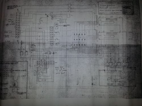
at some point I will get the print scanned into a hi rez copy but it is a Dsize
Posted by Bill Yacey (Member # 6102) on 01-14-2014, 12:42 AM:
"Usually we would not modify the lamphouse (to avoid future confusion), adding the 120V power feed and a 120V coil relay on lamphouse wires 5 and 6 (the 120V "turn on" power to a Strong rectifier) and a NO contact controlling the rectifier. If you see a relay in the rectifier wired to the contactor control terminals that's what has been done. Put the lamphouse power (ground plus 120VAC across lamphouse terminals 2 and 4) on a separate 15A breaker, do not simply run it from one leg of the rectifier 208 without any fuse or breaker. If something goes wrong, power from the rectifier 40A breaker can do a lot of wreckage and it will be violating several electrical codes."
This is essentially what I ended up doing;I tied the lamphouse saftey lockout switch in series with the lamp switch and used that to close the circuit for the contactor in the Allanson supply. I stole 120V from the Allanson 120V 2A auxiliary winding on the terminal blocks to power the fan and HV igniter circuit. Everything seems to be working fine, and I believe this will be far more reliable than the Strong 61001 power supply.
The 3 phase rectification should provide a lot less ripple too, compared to the original Strong.
Thanks to everyone for all the info; if you ever get that schematic scanned I certainly wouldn't mind having a copy. For now though, I believe I've got it figured out.
"Allanson Power Supply is a saturable reactor design "
I figured this was the case when I saw the oil filled cap inside. I didn't scope the ripple after the rectifiers, but I'd be willing to bet that it's closer to a square wave than a sawtooth.
Posted by Gordon McLeod (Member # 33) on 01-14-2014, 10:17 AM:
Typically the DC was very smooth there is scrib;led notes on that drawing of mine to boost the noload voltage
Also the originals had scope matched diodes so if one fails replace them all with 75amp ones
Powered by Infopop Corporation
UBB.classicTM
6.3.1.2