This is topic Kinoton Dual Basement Reader Question in forum Film Handlers' Forum at Film-Tech Forum ARCHIVE.
To visit this topic, use this URL:
https://ft-forum.com/ft/cgi-bin/ubb/ultimatebb.cgi?ubb=get_topic;f=1;t=011691
Posted by Jonathan Wood (Member # 4614) on 08-01-2014, 01:55 PM:
Hello, this is a quick question for a Kinoton expert. On the analogue board , was it standard practice to connect just one of the cells grounds as in the pic below. If so I was wondering why? I am making up a lead for a cinemeccanica dual basement reader and was wondering whether I should connect both grounds or leave one floating ? [IMG][/IMG] 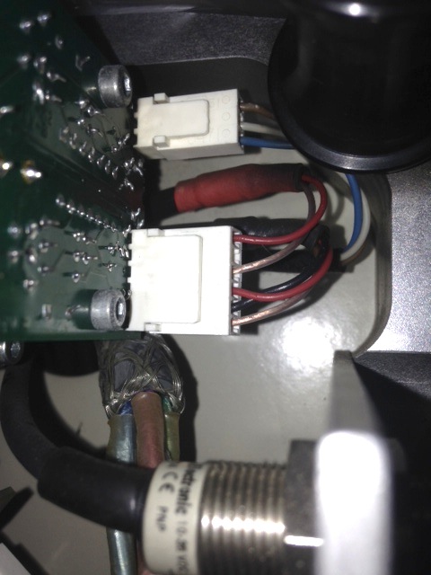
Posted by Mark Gulbrandsen (Member # 72) on 08-01-2014, 02:18 PM:
IMHO it would depend of the ground on the PCB is common or independent per channel. If independent per chan then you want two, if common just one.
Mark
Posted by Jonathan Wood (Member # 4614) on 08-01-2014, 02:41 PM:
Thanks Mark, I don't know to be honest, but each channel has a separate two core shielded cable ( L/R) so on my machine only one of the cables (R) ihas it's shield connected to ground. There is slight hum on the ungrounded channel but it's not noticeable with the sound on ?
Posted by Alastair Bowlie-Evans (Member # 8327) on 08-01-2014, 05:25 PM:
Check with ohm-meter between the ungrounded pin and the grounded. You should have continuity.
Kinoton prob didnt ground both to avoid hum-loops. If you have hum, ground the ungrounded lead to the ground of the other lead, check sound for hum.
If no good, try grounding to the unused pin....
Something you just need to try out....
Posted by Jonathan Wood (Member # 4614) on 08-01-2014, 05:39 PM:
Thanks Alistair, will try it out.
Posted by Sam D. Chavez (Member # 1841) on 08-01-2014, 06:00 PM:
If memory serves, this is a balanced output. There is only one audio not chassis ground on this PCB and this needs to be connected to the 650 or other proc. ground on the 9 pin D sub. The shield should be used for this connection. The Black and Red wires should be the - and + for both left and right inputs. This keeps the lines balanced.
Posted by Jonathan Wood (Member # 4614) on 08-02-2014, 01:05 AM:
Thanks Sam, that makes sense as that describes what I have. Just wondered if someone had done some tinkering in the past and not wired it properly.
Posted by Pete Naples (Member # 761) on 08-02-2014, 02:03 AM:
All sounds fine to me.
A lot of processors didn't have a ground per channel connection. Just one for each projector.
Posted by Jonathan Wood (Member # 4614) on 08-02-2014, 07:14 AM:
Thanks Pete.
Out of interest what happens when you use a PSU that doesn't have a ground terminal for the pre amp 15v supply? On the kinoton PSU there's a ground terminal for the pre amp 15v supply which is connected both ends . I'm going to use a Kelmar PSU for the other projector and there is no ground connection (that I can see) for the 15v supply to the pre amp ? Do I just connect it on the pre amp PCB (3 pin connector) and leave it floating at the PSU end?
Cheers
Posted by Louis Bornwasser (Member # 3063) on 08-02-2014, 07:18 AM:
In the States, I have never used the power supply grounds for anything. If you can do it without hum, then don't use them. Less is more, sometimes.
Posted by Steve Guttag (Member # 268) on 08-02-2014, 07:58 AM:
Some basics here...
A true differential output needs no ground reference. Think transformer...it need not be center-tapped to ground for it to work (balanced)...it merely provides the potential difference.
Its noise immunity comes from that it is a differential signal such that if the input is also differential, you have a high common mode rejection since anything that hits both wires (why they are twisted) will be of equal potential on both wires and will be rejected since they are not differential.
You'll find that the common terminal on both outputs of that board, like Kelmars (I think that it is a stock Dolby board, like the Dolby Digital reader board...it sure looks like the Kelmar board) is the same. You can't really call it a ground because there isn't really a ground reference to it. It should be at the signal reference potential. The wire Kinoton has going to it is a shield wire. A valid way but not my preferred way.
Ideally, one should use shielded wire but NOT terminate it at the cell end. The cell end has no reliable ground reference in a film projector (this is true for most every film projector throughout their history). As such, it has no draining ability for the screen of the cable. Ideally, you DO want the cell end to be floating anyway because you WANT it to be at the same reference potential to your sound system. This will avoid hums/noises from "Ground loops." Prior to the reverse reader craze, the solar cells did a nice job of not providing any ground reference.
You want the cell wire to have its screen tied to a good ground to be effective and that is best done at the sound processor end where there is likely a good earth if the system was installed properly.
Now since these are not transformer isolated systems and are electrically balanced, there is going to be that reference terminal on the cell board...what is best is to run a dedicated wire of reasonable size (the further away from the sound head, the larger the gauge) to bring the cell board to the same potential as the sound processor. You want ZERO current flow on the ground reference.
I can tell you with many successful installations with Kinoton that you will achieve your quietest optical systems in this manner.
Note too, the part of the system you are looking at in your picture goes to a terminal strip mere centimeters away. The fact that they are using the shield as both a shield and reference is of no consequence. There is NO way that one channel is noisier than the other due to how this is wired.
The reference power for both channels is the same and thus both channels share the same reference so the two terminals are identical. I'm sure the design of the board is for those that would make home-runs from each channel using 2-cond/screened cable so that the screens from each channel could be tied at the board. It is a common practice though it is not one that I, personally, recommend for the reasons listed above.
Posted by Jonathan Wood (Member # 4614) on 08-02-2014, 08:53 AM:
Thanks Steve for taking the time to explain that, I appreciate it.
I knew that you were supposed to leave one end floating which is what sparked my curiosity in the first place when I saw the sound head wiring.
Just to clarify then , when I make the new lead up leave both shields floating at the cell end and just connect one to the CP ground tag, (I will be using a CP55 initially)?
When you talk about a separate wire to bring the board down to the same ground reference as the processor, do you mean connect a wire from the shield/ground pin on the PCB directly to earth ? Could I just go inside the machine and attach it to the main chassis ground ?
Thanks again.
Posted by Sam D. Chavez (Member # 1841) on 08-02-2014, 12:10 PM:
What Steve says about running a separate wire between reader board and the cinema processor is correct but I have used the shield(s) in the left and right signal conductors and tied them to the reader audio ground as well as the cinema processor end. Worked well for BACP readers.
Posted by Steve Guttag (Member # 268) on 08-02-2014, 05:55 PM:
Jonathan:
There are two different factors in play here. There is the electrostatic shield...that you want to drain to earth. That is what makes a shield work.
The other factor is having all parts of the sound system on the exact same reference (whether that is true Earth ground or not). The fact that they are often the same thing confuses people. Depending how hard your shield is working affect how well using it as the reference wire is. By definition (well, Ohm's law) if there is ANY current flow on a wire, then there will not be the same potential at each end. Tying the shield at the cell end can potentially increase noise as you are putting the thing that is there to catch noise right on your reference terminal.
It is the difference between "getting away with it" versus doing it properly.
For what its worth, I've found that Belden 8723 functions VERY well as a cell cable. It has two pairs in it with a common drain wire. But if you want to go esoteric, you can always use two runs of star-quad cable.
The CP55 uses the CAT240 preamp module which has a transformer input. I don't recall if it has any reference on its input.
Posted by Sam D. Chavez (Member # 1841) on 08-02-2014, 10:13 PM:
I always use 8723 as Steve says for a number of reasons including the single drain.
CP55 is found with 240 transformer input as well as the 240A active balanced card. There are times the 240 will work perfectly where the 240A will not. The 240 does not care if there is a true ground, the 240A does care and will not work if there are certain wiring faults.
Posted by Pete Naples (Member # 761) on 08-03-2014, 11:03 AM:
Amen Sam!
I remember some years ago a trouble call to Perth Playhouse, a Fedi 35/70 XT projector with a stereo cell and a CP55. The complaint was in optical only surround was working but bypass was OK.
I ruled out Cat222 as it happened in 04 & 05 with the SRA5 installed, by swapping I ruled out Cat150 and Cat243. I was now pretty stumped so in frustration I swapped out the Cat240A for a Cat240 I had in the car. It's now working in 01 but still surround only in 04/05. EH? On the 'scope Cat97 L-R appeared mono'ed with the Cat240A, but OK on the Cat240... Further EH?
So Mono got them through the night and I returned the next morning to do battle once more. After a chat with an older and wiser colleague I looked at the cell wiring.... There was the black wire on the cell waggling in mid air. Some extremely deft soldering with a very fine tipped iron and all was well. I don't think I could solder that now. My eyesight is still perfect but my patience is not.
Posted by Steve Guttag (Member # 268) on 08-03-2014, 11:36 AM:
I thought I explained all of that above? The difference between transformer (isolated) versus electrically balanced systems with differential outputs and the need (or not) for a signal reference.
On a conventional solar cell, the "-" is common to two cells so if it is lifted, you will be using the both cells in series, effectively (think lifting a neutral in an electrical power circuit...you suddenly have 208/240 in a USA system with the loads deciding just how much juice goes to each circuit).
You also don't want to tie the "-" of the CAT240A to ground either.
If you want to feed a line-level source into a CAT240A (or most any other cell input), it is safest to take a PAIR of 47K resistors per channel...even from unbalanced sources use one resistor between "-" and the low side of the line-level source and one resistor between the "+" and the high side of the line level source. The 47K will typically get a 10dB source in the right ballpark on level as well as deal with the active balance input.
Powered by Infopop Corporation
UBB.classicTM
6.3.1.2