This is topic need a wiring diagram for Hertner Transverter in forum Film Handlers' Forum at Film-Tech Forum ARCHIVE.


To visit this topic, use this URL:
https://ft-forum.com/ft/cgi-bin/ubb/ultimatebb.cgi?ubb=get_topic;f=1;t=011774

Posted by John Eickhof (Member # 323) on 01-25-2015, 07:12 PM:
 
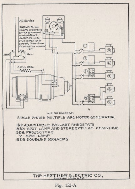
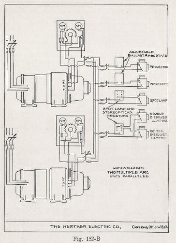
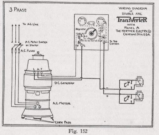
I've dug through all my RCA & Altec service manuals and can't come up with a wiring diagram for a Hertner Transverter model 40/80 carbon arc motor-generator, I am going to set one up in my museum's 1940s E7/peerless booth for one KW arcs. Can anyone email me a JPG of the wiring info, especially the field control rheostat circuit? Thanks all, I know there's a few old timers left out there!
 
Posted by Jim Cassedy (Member # 4115) on 01-25-2015, 08:18 PM:
 
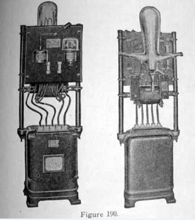
Don't know if these will be of any help to you.

These images are from my 1927 copy of the "Richardson's
Projection Handbook" - - - Pages 516. 517 & 518
 -

 -

 -

If you need higher resoloution images, or if you'd
like to have scans of the entire pages, which have
lots of text info about the transverters, PM me and
I'll send them to you. Somewhere around here I'm
pretty sure I have an actual transverter manual,
but I'm on my way out the door to do a screening,
so I can't go 'digging' for it at the moment.

Hope these images are at least some hlep to you, for now. [Smile]

-jc-
 
Posted by Steve Guttag (Member # 268) on 01-26-2015, 06:44 AM:
 
Well that is kinda cool.
 
Posted by Steve Kraus (Member # 476) on 01-26-2015, 10:24 AM:
 
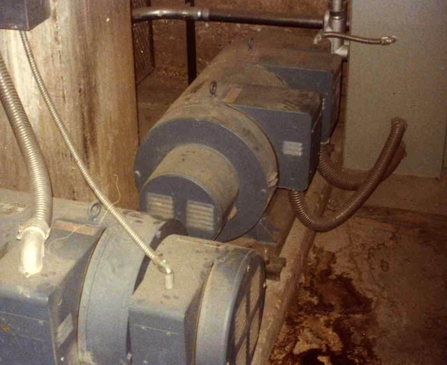
In that case you'll enjoy this. These are motor-alternators making 400 Hz. to run a couple of Control Data mainframes circa late 1970s. 400 Hz. is easier to rectify into smooth, low voltage DC but if you need M-A's to make it, it might be easier to just deal with 60 Hz. So from what I could gather the real reason for the M-A sets was to isolate from power line glitches, ride out momentary outages and having the output side be 400 Hz (with smaller transformers & filter at the rectifier end upstairs) was just a side benefit.

 -
 
Posted by Pete Naples (Member # 761) on 01-26-2015, 03:54 PM:
 
I was recently talking to a friends grandfather, an elderly gent who'd served his country in the RAF.

Apparently the legendary Lancaster, Halifax and Lincoln heavy bombers had a similar device on board to provide power for the radar later in WWII. With aviation being fanatical about weight saving I was somewhat surprised, he said it was the best they could do at the time.
 
Posted by Frank Cox (Member # 6258) on 01-26-2015, 04:27 PM:
 
The most striking thing about the Unbroken movie (to me, anyway) is how minimally equipped the bombers are. Being used to seeing the modern war movies where there's all sorts of armour and hi-tech gadgetry, those bombers (assuming that it's a historically accurate depiction) were pretty much the minimum possible mechanical components that would get a load off the ground. No armour worth mentioning and a few guys just hanging out the sides in the open air using very basic machine guns equipped with ring sights and a belt of ammunition. No such thing as a seat belt or even a seat for some of those folks.
 
Posted by Louis Bornwasser (Member # 3063) on 01-26-2015, 05:13 PM:
 
Larger aircraft still uses 400 Hz AC.
 
Posted by Gordon McLeod (Member # 33) on 01-26-2015, 07:13 PM:
 
After the war the generators were sold as surplus and many ended up being used as arc welder we had one on our farm
 
Posted by John Eickhof (Member # 323) on 01-26-2015, 09:23 PM:
 
400 Hz was used primarily on all aircraft made in USA during WW2 for communications, radar, IFF and navigation as the higher frequency allowed for much smaller and lighter electronics ie: transformers,chokes etc. The laminated cores were considerably smaller for the higher frequency without developing additional heat loss. Electric motors also were very small and efficient.
 
Posted by Steve Kraus (Member # 476) on 01-28-2015, 09:21 AM:
 
There are probably still plenty of elevators running on MG sets. Many (most?) have been updated but it's a larger undertaking than simply dropping in a transformer & rectifier because field current is part of the control system.
 
Posted by Mark Gulbrandsen (Member # 72) on 01-28-2015, 09:56 AM:
 
Aircraft use 400 hz because everything associated with it is smaller and lighter.

Mark
 
Posted by Pete Naples (Member # 761) on 01-28-2015, 09:58 AM:
 
It never ceases to amaze me the wealth and breadth of knowledge us projection dinosaurs have on tap!
 
Posted by Jeff Taylor (Member # 443) on 01-28-2015, 11:01 AM:
 
All the electronics on WWII American subs were also powered by MG sets even under diesel power.
 
Posted by Charles A. Petty (Member # 3458) on 01-29-2015, 08:59 AM:
 
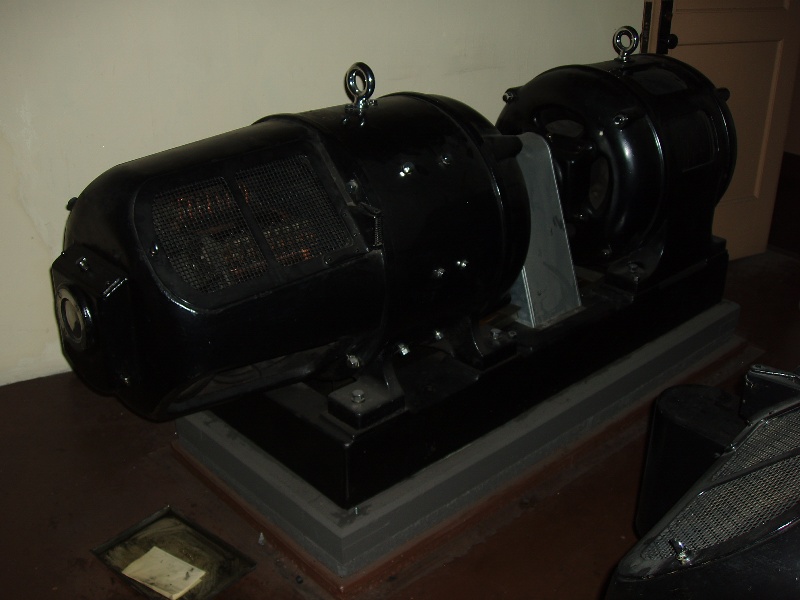
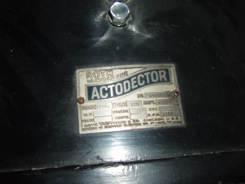
One of the two original Actodector MG sets still in use at the Oakland Paramount theater.
 -
 
Posted by Jim Cassedy (Member # 4115) on 01-29-2015, 10:37 AM:
 
quote: Steve Kraus
There are probably still plenty of elevators running on MG sets
One of the screening rooms I work at is located in a building that dates back
to 1914. The elevator control system probably dates back to the early 1930's.

Big friggn'-huge motor generators, and thyratron control tubes, and more
relay racks than you'd find in an old telephone company switching office.

I recently took a friend down to the basement to see it and he was in awe.

Next time I'm there, I'll try & get some pictures!
 
Posted by Jeff Taylor (Member # 443) on 01-29-2015, 01:12 PM:
 
You should have seen the lighting control room in the basement level at RCMC. They claimed to be the largest volume purchaser of vacuum tubes in the world after NASA.
 
Posted by Stephan Shelley (Member # 8587) on 01-29-2015, 05:53 PM:
 
Those are Century MG sets at the Paramount Oakland. Two of them. One of the two is used for movie classics with Strong Excelite Carbon arc lamphouses.
 
Posted by Charles A. Petty (Member # 3458) on 01-29-2015, 08:04 PM:
 
There are two Roth Actodector motor-generators in the basement at the Oakland Paramount, not Century. See attached photo of the data plate.  -
 
Posted by Stephan Shelley (Member # 8587) on 01-29-2015, 08:35 PM:
 
Check the motor side. Century 3 phase motor.
 
Posted by John Eickhof (Member # 323) on 01-29-2015, 09:05 PM:
 
Yes they are Century Electric Motors ( standard on Roth equipment ) However, CE was not affiliated with Century Projector corp. The entire motor-generator set was sold as Roth and the Actodector trademark. ( just like Transverter was the tradename for Hertner Electric ) Hobart, GE, Continental Electric, Martin, Robin Imperial, and Westinghouse also made DC arc lamp motor gennies, several used their own electric drive motors, others contracted out for their motors. Usually the two piece coupled types used various motor suppliers. The field controls, meter panels, ballast resistors, and accessories were generally made in house by the generator maker. IR international Resistor supplied most of the actual high current resistors though.
 
Posted by Charles A. Petty (Member # 3458) on 01-30-2015, 03:37 PM:
 
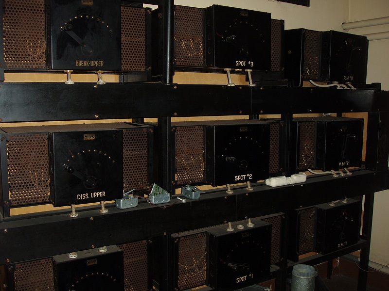
Speaking of high current resistors...
 -
 
Posted by Stephan Shelley (Member # 8587) on 01-30-2015, 09:54 PM:
 
Anybody have a pic of a synchronous rotary converter used for arc power? Basically they are a mechanical rectifier. I know of some for railway power. I have heard that some theatres used them as well. A little more efficient than MG sets.
 
Posted by John Eickhof (Member # 323) on 02-01-2015, 11:57 AM:
 
The only synch converter I know of was the Ashcraft Cyclex system that used an electric motor driven AC converter that produced 96 cps 3 phase power fed to special static transformers (Ashcraft terms as control units) for each arc lamp that used a pair of 7mm ac carbons. The light pulsated at twice shutter interruption thus when in synch with the projector it produced a very smooth, intense flickerless light. The transformers changed they the arc, changes 3 phase to two phase so one phase feeds the arc in each lamp, and an adjustable air gap coil which in essence is a magnetic valve between the primary & secondary that allows the arc feed motor accurate control of the arc length. Basically if the gap is set correctly, the feed motor would automatically keep the arc at the correct gap. I have never operated these lamps but have talked with projectionists and technicians in the past who have and they said the original set up was tedious but once completed the arcs were very stable and needed no attention from the projectionist after they were struck.
 
Posted by Robert Koch (Member # 3728) on 02-03-2015, 03:15 PM:
 
John
I dont know who the old timers you talked to concerning the Cyclex;
but Im older than dirt,and I ran Cyclex for non other than Ray Syufy and his parents, Bill and Pauline at the Rita in Vallejo before I went overseas. My experience was different than your other old timers. You couldnt turn your back on the damn thing cause it was always blowing out.
 
Posted by John Eickhof (Member # 323) on 02-03-2015, 09:49 PM:
 
Hi Bob, What was usually failing? Or the weak points? I had never operated nor worked on one but Jim Gillespie in southern cal had operated the lamps and there were a few set ups in the LA area he said the biggest problem he remembered was adjusting the variable speed pulley on the drive motor to match the actual shutter speed of the projector mechanisms. (they had to average it because there were differences in sped of both projectors typically) It definitely was an interesting principal! By the way, do you have a wiring diagram for a hertner M40-80 1kw motor generator in your RCA service bulletins?
 
Posted by Robert Koch (Member # 3728) on 02-04-2015, 02:31 PM:
 
Sorry John; all of my RCA stuff is gone including my ERPI BIBLE, which I should have held onto and profited from, but foolishly didnt.
 
Posted by Stephan Shelley (Member # 8587) on 02-04-2015, 04:01 PM:
 
I think you are talking about a different type of converter than I was referring to. I am talking about a rotary converter. Has multiple phase slip-rings on one side of the armature and a a commutator on the other. One end of the windings on the armature is on the one of the slip rings and the other on a commutator bar. The armature spins in sync with the AC frequency so that when the AC peak hits the commutator bar is under the positive brush and when the negative dip hits it is under the negative brush. You rectify existing AC current. I know of some railway 600 V DC machines in working condition and are used at time in operating museums.
 
Posted by John Eickhof (Member # 323) on 02-04-2015, 07:37 PM:
 
Thanks Bob, As for the converter, I can't say I've ever seen anything like it in a theatre setting. Interesting idea, so by multiplying the phases it puts out direct current? I wonder how smooth the DC is? Amount of ripple, etc?
 
Posted by Stephan Shelley (Member # 8587) on 02-04-2015, 08:02 PM:
 
The railway one has 2400 volts 3 phase going into a transformer that has combination delta and star connections to give phase shifts and puts out 6 phase 440 v AC. The rotary has six sliprings and multiple poles so there are more than two sets of dc brushes. At least 6 sets. This unit was built as a portable booster unit. It would detect the drop in voltage cycle itself on and turn itself off later. 1920s relay tech. GE made it for the Sacrament Norther RR.

I have heard of smaller units for theatres. I heard one problem was if it is left to start on its own you never knew the polarity it would come up as. The railway automated one starts as a repulsion motor at half voltage. As part of the start-up it pluses the field so that it locks in the same polarity when it locks in as a sync motor. I have heard projection booths that used them had polarity reversing switches.

They should be as smooth DC as a generator. Generators are really stationary field alternators. It is the Commutator that makes it DC. The ripple has a lot to do with the number of field poles and brush sets. Same with the rotary converter and also in the case of the rotary converter the number of phases going in.
 
Posted by System Notices (Member # 2357) on 05-07-2016, 12:34 AM:
 

It has been 457 days since the last post.


Posted by Steve Kraus (Member # 476) on 05-07-2016, 12:34 AM:
 
Bringing up this thread to ask if, before silicon rectifiers, were arc lamp supplies always M-G sets (AC motor spinning DC generator) or were they ever rotary converters like Stephan Shelley was discussing.

Like this:

https://en.wikipedia.org/wiki/Rotary_converter

I'll summarize in case the link ever fails that it was like a motor and generator merged into one but some of the energy can go directly (via brushes, slip rings, and commutator) while some moves mechanically (compared to an M-G where all the power goes through mechanically). They were common for electric railways.

I'm wondering if maybe the power output wasn't smooth enough for projection arc use where non smooth power would cause flicker as it interacted with the shutter. Or maybe they were only practical in very large sizes and for lamps an M-G was more cost effective.
 
Posted by Jim Cassedy (Member # 4115) on 05-07-2016, 01:32 AM:
 
quote: Steve Kraus
were arc lamp supplies always M-G sets (AC motor
spinning DC generator) or were they ever rotary converters

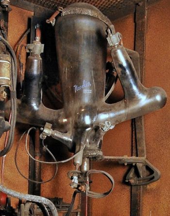
In the very early days, huge mercury vapor rectifier tubes were
used to supply the DC for the arcs. I actually encountered a few
of these still in use in the early 1970's! Here's a front & rear
picture from a 1926 projection manual I have in my collection:
 -

The tubes looked like some apparatus out of Frankenstein's lab.
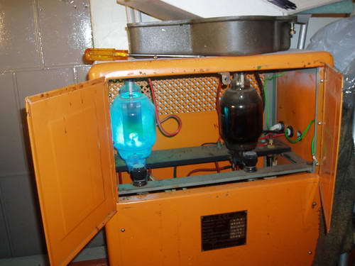
I came across one of these mercury rectifiers in an old theater:
 -
 
Posted by Stephan Shelley (Member # 8587) on 05-07-2016, 12:42 PM:
 
I have heard from others that on rare occasions rotary converters were used in theatres for the DC supply for the arc lamps. The big drawback is they don't always sync the same and the polarity is a 50/50 chance of being correct. Usually theatres that used rotary converters would have a polarity reversing switch.

In the case of the railway power rotary converter there is a startup sequence done by a drum switch sequence and the motor that drives the drum switch also runs a small generator that polarize the field on startup so it always sync the correct way. Sacramento Northern portable sub 1 is the one I am familiar with and was designed to run automated and unattended. When the voltage dropped below the threshold level for an specific amount of time it would fire up and after the train passed shut down again all on it own. This is late teens electro/macanical tech. In this case made by GE.
 
Posted by Steve Kraus (Member # 476) on 05-08-2016, 12:52 AM:
 
Funny you mention that as the Illinois Railway Museum is just outside the little hamlet of Union, Illinois and utilizes about 4.5 miles of the right of way of the old Elgin & Belvidere electric interurban (trolley) line which folded around 1930. Union warrants a footnote in trolley history as the location of the first automated substation, working just as you describe.
 
Posted by Stephan Shelley (Member # 8587) on 05-08-2016, 01:39 AM:
 
The one I am referring to is now at the Western Railway museum near Rio vista CA. Years ago it was the sole source of 600 volt DC power for the museum now it is in standby service. I think they fire it up once a month. A sister machine also from the Sacramento Northern but was a fixed location is at the railway museum near Pairs CA. Interestingly the build that that rotary was in is at the Western Railway museum and houses a solid state supply. The Western Railway museum operates a section of the Sacrament Northern.

Back to the mercury valve rectifiers they were also used for railway power. No glass but metal enclosers. There is also the sister Ignitrons developed by Westinghouse.
 
Posted by Stephen Furley (Member # 1277) on 05-09-2016, 10:17 AM:
 
Those mercury arc rectifiers are tiny. Much larger ones exist, even as glass bulbs. Railways used both types; the Manx Electric Railway retired their last ones just a couple of years or so ago, and even the London Underground had some large glass bulb types, there used to be some in a substion next to one of the stations, and at night you could see the weird blue glow inside. The biggest steel tanks I have seen are 12 anode ones, about two metres in diameter.

There's an old pumping station in London with two very large triple expansion engines and two steam turbine sets, which is now a museum. The electrics are 200 V d.c. The original rectifiers were scrapped, but the museum people managed to obtain suitable replacements from the Royal Opera House of all places.

web page

Still quite small. I believe that the glass bulbs were blown by hand; must have been quite a job.
 
Posted by Tony Bandiera Jr (Member # 2365) on 05-09-2016, 11:52 PM:
 
Here is the link to a video of a large mercury arc rectifier in action..The Manx Railroad on the Isle of Man:

Manx Mercury Arc Rectifier
 
Posted by Buck Wilson (Member # 5885) on 05-10-2016, 12:31 AM:
 
I mean, I know those are "reliable" and "relatively safe" but dear god am I the only one that would not dare go near one of those things??
 
Posted by Alan Plester (Member # 852) on 05-10-2016, 06:53 AM:
 
Fascinating thread and pictures. we had the cage of the old mercury rectifier in the defunct projection room , I often wondered what it really looked like when operating, my old chief, described it as a large octopus, and recalled the day it went bang, nasty mess
 
Posted by Jim Cassedy (Member # 4115) on 05-10-2016, 09:09 AM:
 
quote: Buck Wilson
am I the only one that would not dare go near one of those things??
and
quote: Alan Plester
recalled the day it went bang, nasty mess
No, Buck, you are not alone. The very first theater I was permanently assigned
to had one of these monstrosities. It was a big, high-voltage device in an open
frame crammed into a small booth, and I was always a bit apprehensive around it.

My fears were not unfounded, as one night the thing "went bang" when I came
into work and threw the knife switch that turned it on. I was peppered with
glass shards, and fortunately I happened to be looking away from it when it
exploded or I might have gotten glass (and worse yet- - mercury!) in my eyes.
I was finding little balls of mercury all over the booth for weeks afterwards.

Believe it or not, they had a 'spare' tube, and continued to use the unit for
about another year before they replaced it with a "Sil-Tube" rectifier when
one of the transformer or choke windings in it overheated and began to
belch smoke and then 'flame-out' and burn up.

But as long as they continued to use the old unit, after the 'exploding bulb'
incident, I had always kept my distance and always turned my back to it
when switching it on at the beginning of my shift.
 
Posted by Stephen Furley (Member # 1277) on 05-10-2016, 03:19 PM:
 
I don't mind Mercury rectifiers, but I think I'd keep my hands a bit further away than the man in the video. Xenon lamps on the other hand do worry me.
 
Posted by David Buckley (Member # 2600) on 05-10-2016, 09:14 PM:
 
We had a mercury arc rectifier in our booth until relatively recently:

 -

And, of course, there is the old, now removed, mercury arc based New Zealand HVDC link, some really big mercury arc valves in that! (PDF).
 
Posted by Alan Plester (Member # 852) on 05-11-2016, 05:25 AM:
 
WOW, they be some seriously big tubes.
 
Posted by Stephan Shelley (Member # 8587) on 05-12-2016, 03:51 PM:
 
The Royal Opera house may have had to do with spotlight power. Also some stage houses back in the day like to use DC for incandescent light sources so there is no flicker. There were some places like Shay's Buffalo that had 25 HZ AC. The flicker was noticeable.


Powered by Infopop Corporation
UBB.classicTM 6.3.1.2