This is topic Cinemeccanica Portacine Revisited in forum Film Handlers' Forum at Film-Tech Forum ARCHIVE.
To visit this topic, use this URL:
https://ft-forum.com/ft/cgi-bin/ubb/ultimatebb.cgi?ubb=get_topic;f=1;t=012043
Posted by Ian Partridge (Member # 9377) on 08-21-2016, 04:52 AM:
This is a question about the feed guide roller directly above the gate on a Cinemeccanica 35mm.
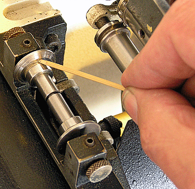 Sprung roller flange pushed apart.
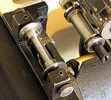 Roller flanges together
The hollow roller comprises of two parts with an internal expansion spring squeezing the two halves together. The film edges are supposed to run between the flanges, but in practice the film loop tends to be expelled slightly by the sprung flange? You can see that a circular groove has been worn previously on the flange bevel in the picture.
I noticed the front grub screw and cone bearing adjuster were tightened-up so that the front flange did not rotate, while the sprung back half could ?
I have adjusted the grub screw settings so that the roller is free to rotate as nature, and possibly Cinemeccanica, intended and also slightly adjusted the internal expansion spring to give less 'squeeze' to the film sides. But the upper loop still tends to dwell outside the flange sides at the bevel ?
Is it possible that the two halves have worn closer together because the cone bearings were locked ? In which case adding a shim washer to the middle would allow the film sides to be guided in the flanges as they should ?
Ian
Posted by Monte L Fullmer (Member # 2797) on 08-22-2016, 02:59 AM:
More like the film path for the trap and gate assembly isn't fully straight-why the film wants to ride up on that one flange.
Please check all parameters in the film path first.
Good luck - Monte
Posted by Marco Giustini (Member # 4544) on 08-22-2016, 07:38 AM:
There should be no or little play between the film and the 'fixed' flange, the one towards the bottom of the picture. Adjust both conical grub screws so that side is barely touching the film. Then - as you already did - adjust the other grub screw so the whole assembly is free to rotate, but with the minimum play possible.
The design of that thing is a joke so it may not be possible to prevent the film from jumping out of the path - particularly when a splice runs through - but it's worth a try.
Posted by Kenneth Wuepper (Member # 1174) on 08-22-2016, 09:34 AM:
The jumping from the "studio gate" can also be caused by an excessively large upper loop.
Posted by Mark Gulbrandsen (Member # 72) on 08-22-2016, 04:56 PM:
If you can acquire a piece of 35mm steel alignment film that would be best.
Posted by Ian Partridge (Member # 9377) on 08-23-2016, 05:04 PM:
I have tried re-adjusting the roller according to the helpful suggestions given. And I appreciate all your knowlegeable forum advice.
I used two thicknesses of film stock which helped with first correcting alignment of the fixed flange of the roller. There is no adjustment for the sprung flange, but as directed, I tightened the grub screw to allow the cone bearing just enough to rotate freely.
On test, the upper loop is now very much improved, weaving in and out between the flanges. Before it was riding up even when inching. I may have left too much loop at the top (but followed the film path diagram) which allowed the loop to flex too much. It seems a mad design.
Ian
Posted by Monte L Fullmer (Member # 2797) on 08-23-2016, 05:30 PM:
Ian, please take a look at this thread that I started back in 2006 on the threading
http://www.film-tech.com/cgi-bin/ubb/ultimatebb.cgi?ubb=get_topic;f=1;t=007823#000000
Maybe give this a try and see what happens.
Good luck - Monte
Posted by Nigel Shore (Member # 3827) on 08-24-2016, 10:09 AM:
Ian. You first take the roller apart. Be very careful not to lose the spring as you take the circlip off. Clean the bore on one half of the roller and the spindle on the other half. With smear of WD40 reassemble the roller. Make sure there is no crud in the point screw holes on both ends and make sure that the point screws are clean. Now the important bit. Refit the roller and using a straight edge (a 6" steel ruler or an aperture plate which is exactly 35mm wide) adjust the outer point screw so the film edge of the roller is exactly in line with the reference (soundtrack) edge of the gate plate. Adjust the opposite point screw so that the roller will rotate freely but with no end float. You will only need to just tighten the 2 grub screws, to hard and they will damage the point screw threads. DO NOT put a shim between the 2 halves of the roller. if it is fractionally too big you will get a dead centre emulsion scratch When running the film should sit into the roller which will only slightly turn. If it is badly grooved you'll need to replace it. Check that the top sprocket is hard against the shoulder on the shaft.
As for the statement that this roller is a joke I disagree. The same roller has been used on every V10/V8/V9/V4/V5, so for about 60 years If it springs freely and is adjusted correctly it works perfectly.
Posted by Leo Enticknap (Member # 534) on 08-27-2016, 09:53 AM:
quote: Nigel Shore
Clean the bore on one half of the roller and the spindle on the other half.
I wonder if doing that would help the thin roller that always sticks just below the top entrance to the chassis on the Norelco AA/Philips DP70 mk. I? I have an ongoing battle with a pair that keep binding, and have to remove them and scrub the roller bore with a Q-tip (cotton bud) soaked in isopropanol, and apply a tiny coating of projector oil to the shaft, every couple of weeks to keep them rotating freely. It's a big film scratching risk if you don't keep a very close eye on it, which I suspect is why that roller was gotten rid of in the mk. II.
Posted by Dave Macaulay (Member # 813) on 08-27-2016, 07:35 PM:
WD40 is a very poor lubricant and will turn to gum quickly. Use sewing machine or clock oil, 3 in 1 electric motor oil if desperate. The intermittent oil is OK but a bit thick... use just a small amount.
Posted by Kenneth Wuepper (Member # 1174) on 08-27-2016, 07:40 PM:
There is a product called "Dry Slide". If you apply it with a small cotton tip and sparingly it will function very well and for a long time. It does not gum or flake as other products have in the past. It is also useful on the fire traps where lubrication to prevent scratches is very critical.
Posted by Ian Partridge (Member # 9377) on 08-28-2016, 08:16 PM:
From the information given I decided that I should start again with the roller. On disassembling I noticed that the inner shaft bearing surface was dull and rough. Therefore the two halves did not spin freely as would be expected. The crevices of the flanges were also dull.
I used a small dab of the "fine" grade grey polishing powder from an old car valve grinding kit on a small square of tissue and simply rubbed away the roughness with forefinger and thumb, imparting a brightly polished finish to the roller halves of the shaft and shell and flanges. On the flange sides with the radial grooves worn by the film edges, I applied firm pressure with a thumb nail and these marks polished out qickly and easily in a couple of minutes. Then thoroughly rinsing the parts in isopropyl alcohol solvent before reassembly and a drop of light oil.
I used a printers' type scale (28mm wide)as a straight edge for alignment of the flanges. On a brief test with film the curve of the upper loop now dwells as it should between the roller flanges without riding up. So it appears that it was the unpolished roller dragging causing the film edges to jump out.
Which follows on to my further Portacine question concerning the framer adjustment? On the PC 35 diagram legend it shows the lower film path with the film fed between the two rollers at the lower loop? Since adjusting the framer in effect reduces or increases the size of the upper loop. In the position shown in the threading diagram the framer is shown pulled down to its fullest extent.
I would assume that the framer should be initially set exactly half and half way to allow for any necessary framer adjustment both up and down ?
Ian
Posted by Fredrik Sandstrom (Member # 8171) on 08-29-2016, 02:36 AM:
quote: Ian Partridge
I would assume that the framer should be initially set exactly half and half way to allow for any necessary framer adjustment both up and down ?
I prefer to set it in the extreme "up" position, to let the maximum number of intermittent teeth engage the film. Provided you thread in frame, and there are no incorrect splices in the film, this still gives you enough room for adjustments to fine-tune the framing. If I have reason to believe I will need to make bigger adjustments, I thread with the framer set one perf down. I don't like running in the extreme "down" position, as it seems to me the film is barely touching the intermittent sprocket then.
Posted by Ian Partridge (Member # 9377) on 08-29-2016, 08:19 PM:
 Cinemeccanica Portacine threading path diagram label.
Now I can understand why these are placed at 12 o'clock and not 9 o'clock.
I have noticed that there is also an inspection hole for inching up to align with a red dot when threading so that the frame dwells in correct position with the gate aperture.
Following the film path to just before the sound drum, there are three tension/guide rollers. The fat middle one is static, fixed, and does not rotate ? I assume this correct and is to create a slight 'drag'to keep the film tight and smooth around the sound drum ?
Ian
Posted by Fredrik Sandstrom (Member # 8171) on 08-30-2016, 02:19 AM:
quote: Ian Partridge
I have noticed that there is also an inspection hole for inching up to align with a red dot when threading so that the frame dwells in correct position with the gate aperture.
I think the purpose of the red dot is for timing the shutter with the intermittent (for example after replacing the drive belt), but sure, you can use it when threading too if you find it helpful.
quote: Ian Partridge
Following the film path to just before the sound drum, there are three tension/guide rollers. The fat middle one is static, fixed, and does not rotate ? I assume this correct and is to create a slight 'drag'to keep the film tight and smooth around the sound drum ?
Yes, that is correct, but unfortunately it does not work as well as it should. Many Portacine users (myself included) have noticed that especially polyester film will have flutter in playback. If you experience this problem, take a look at how I solved it: Portacine soundhead fix
My solution involves replacing one of the rollers with a sprocket, with an adjustable friction to provide suitable drag.
(Should my entire text be posted here for the forum archive? With or without images?)
Posted by Ian Partridge (Member # 9377) on 08-30-2016, 04:09 AM:
Fredrik, thanks for the information and link to your page about your solution to the flutter problem.
I remember, years ago, lining up to the red dot when threading Westars. We had the instruction manual as the machines were new. Although I cannot remember if this was from following the Westar threading directions.
My Portacine has a red laser sound head about which I need guidance about what type it is and how it works ?
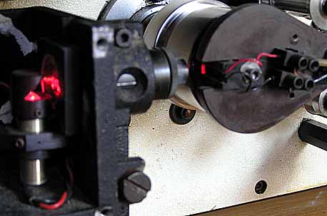 Portacine sound module
The laser module is: " iLEE 0115-01-92-01 B1121 " At present I am using a Cinemeccanica C55PT amp with the internal switch set to 'DIODE'
Ian
Posted by Monte L Fullmer (Member # 2797) on 08-30-2016, 05:17 PM:
quote: Fredrik Sandstrom
I prefer to set it in the extreme "up" position
My practice, in running CINE Units (and all geneva base movements) Projectors is having the unit in the middle position of the travel so the assembly is in more relaxed position to allow the operator to choose to go up or down, or even the minute framing adjustments when correcting a frame issue.
Placing the operation at it's extreme allows a form of stress to where the assembly wants to move to a more relaxed position.
quote: Ian Partridge
My Portacine has a red laser sound head
More looks like that the filament type exciter lamp was removed and an LED light replaced it, for the pickup is no way an IR Camera, but just a solar, white light reader.
We call it a JAXLight changeout (A unit that just plugged into the exciter lamp socket and a red light passed through the slit lens), where the slit lens wasn't effective enough to handle the red light beam causing a major drop in output voltage off the solar reader. With this drop, the preamps had to be cranked all the way open where one got a lot of noise as the results in the sound.
Red light was effective with the cyan soundtracks, where standard exciter lamps were horrible with the cyan soundtracks, why you got the LED conversion.
Posted by Fredrik Sandstrom (Member # 8171) on 08-31-2016, 01:09 AM:
quote: Monte L Fullmer
My practice, in running CINE Units (and all geneva base movements) Projectors is having the unit in the middle position of the travel so the assembly is in more relaxed position to allow the operator to choose to go up or down, or even the minute framing adjustments when correcting a frame issue.
Placing the operation at it's extreme allows a form of stress to where the assembly wants to move to a more relaxed position.
I was talking about the Portacine specifically. I don't understand what, on that machine, would cause more "stress" in the extreme up position that I favor. If I set it in the middle like you suggest, the film will have some steep turns to go through (and worse still in the extreme down position). The smoothest film path would be achieved by removing the framing mechanism altogether, and something very close to that situation can be achieved by setting it to "extreme up".
quote: Monte L Fullmer
More looks like that the filament type exciter lamp was removed and an LED light replaced it, for the pickup is no way an IR Camera, but just a solar, white light reader.
I've seen laser units just like that, so if Ian says it's a laser I'm sure it's a laser. They are typically used with standard solar cells for pickup.
And Ian, it looks like you have the original mono cell fitted. If you want stereo, you need to change it to a stereo cell, or (better) convert to reverse scan.
Posted by Christos Mitsakis (Member # 143) on 08-31-2016, 04:19 AM:
Ian,
The laser is an ACL-9 AUDIO-CINE WALTER VOIGT AG, for Cinemeccanica and Prevost soundheads.
The original web page I think is down but have a look here
Christos
Posted by Ian Partridge (Member # 9377) on 09-02-2016, 01:12 AM:
The laser light beam comprises of a curious mosaic grid pattern and is rectangular, not a slit shape. It appears like a gauze is placed in front of the lens element when the module is lit, but it is an illusion. It is a normal glass lens. A square-shaped beam arrives at the photo diode.
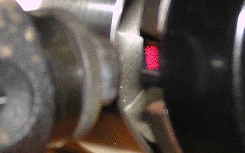 The laser beam arrives at the photo diode.
A similar pattern shows on the front element of the lens tube that is not possible to photograph as the camera gives a scanning line which looks like the conventional slit shape.
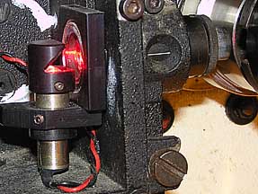 Laser sound module.
The rounded glass below the right-angled mirror is divided in the middle ? The Voigt ACL-9 sound module diagram shows a slit-shape, not a rectangle ?
Ian
Posted by Kenneth Wuepper (Member # 1174) on 09-02-2016, 09:26 AM:
Ian,
Please place a piece of properly tensioned film around the sound drum. Then look at the light image on the sound track area.
Dirty optics or maladjusted scanning beam can cause some strange effects.
There is a slit mask in the optical cell and it can be out of adjustment as well. This whole assembly is very critical to the reproduction of optical sound.
Check in the warehouse for service instructions for a typical sound reader. Your problem may be simply cleaning or improper adjustment. Do not attempt adjustment without the proper film loops and test instruments.
Hope this helps.
Posted by Ian Partridge (Member # 9377) on 09-02-2016, 03:05 PM:
Kenneth you are correct, and Christos is also right that it is a Voigt ACL-9 laser module. I was looking at the diffuse slit image on white leader and not on the soundtrack itself. It seems to be in OK alignment as much as I can tell without test tracks.
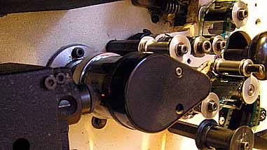 Sound slit image focussed on film track.
The sprung roller above the gate is now functioning as it should with the film edges between the flanges. shown in the photo below. I have polished the other rollers in the film path which some had gummed up and dull arbors so they did not spin freely when flicked.
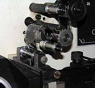 The sprung roller above the gate shown with the film edges now running between the flanges.
Ian
Powered by Infopop Corporation
UBB.classicTM
6.3.1.2