This is topic Still seeking the correct threading diagram for an FP20 in forum Film Handlers' Forum at Film-Tech Forum ARCHIVE.
To visit this topic, use this URL:
https://ft-forum.com/ft/cgi-bin/ubb/ultimatebb.cgi?ubb=get_topic;f=1;t=012073
Posted by Ian Griggs (Member # 9542) on 10-14-2016, 02:43 AM:
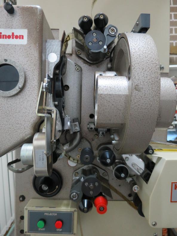
This question has no doubt been asked before, but I have several manuals for the Kinoton FP20 and FP30, but none of them are for my machine. In particular I just need the correct threading diagram.
This projector is C1990 with the serial number 4313, and has the red film break sensor roller. Glad for any assistance. I just want to make sure I am threading the correct way to avoid any damage. Many thanks in advance. Picture attached.
Posted by Fredrik Sandstrom (Member # 8171) on 10-14-2016, 08:16 AM:
The soundhead threading is incorrect. The film should go between the sound drum and the spring-loaded roller.
Posted by Sascha F. Roll (Member # 9043) on 10-14-2016, 08:48 AM:
Plus the upper loop is way too big.
Posted by Scott Norwood (Member # 30) on 10-14-2016, 09:12 AM:
Definitely watch that upper loop--the film stripper can easily scratch the emulsion if the loop is too big (as it is in the picture). Newer FP30s have a slightly different upper sprocket arrangement which reduces the risk.
Also, the film is supposed to go in an S-pattern through the two black rollers above the upper feed sprocket and below the holdback sprocket. Which is to say, that it comes off of the feed reel, goes under the roller closest to the screen, over the roller closest to the lamphouse, and through the upper feed sprocket. It should do the same thing after the holdback sprocket. As shown, the upper feed pattern is wrong, while the holdback pattern is correct.
I have not seen the exact arrangement of rollers that is shown before the soundhead. The film definitely needs to go under the spring-loaded "pinch" roller (be sure to get a few spare "O-rings" for this), as mentioned above, though.
Posted by Christos Mitsakis (Member # 143) on 10-14-2016, 12:05 PM:
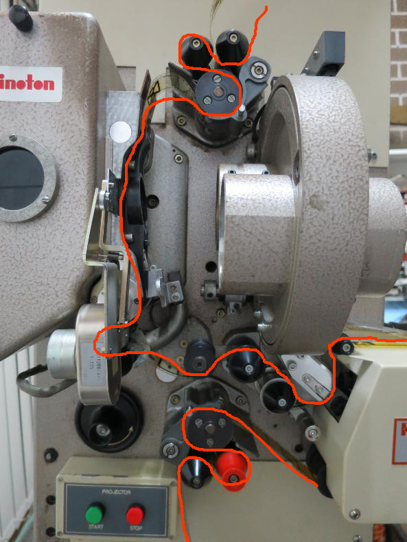
Sorry for the clumsy sketch.
The upper loop should be a little larger than my sketch but definitely smaller than the one pictured.
Posted by Steve Guttag (Member # 268) on 10-14-2016, 05:49 PM:
Yup, I concur!
Posted by Ian Griggs (Member # 9542) on 10-14-2016, 05:51 PM:
Thank you everyone. I meant to say that my diagram was VERY premature, and I knew it wasn't right!
Christos thank you so much. That's a tremendous help and I'm grateful. We can all get on with more important things now hihi.
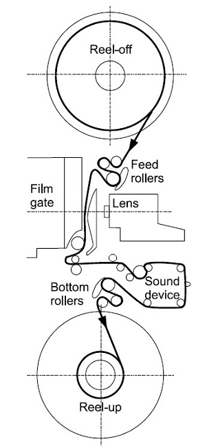
PS Steve where did you get that diagram from? That must be in a manual I've never seen!
Posted by Mark Gulbrandsen (Member # 72) on 10-14-2016, 07:15 PM:
It's basically the same as the PK-60 D is.
Posted by Steve Guttag (Member # 268) on 10-14-2016, 10:59 PM:
Yes, all of the mechanical Kinotons share an extremely similar film path. Kinoton/Philips used the double entrance/exit rollers up until about 2001 or 2002. So if you want to see a manual that has them, you have to go to one of that era. I always made a point of keeping vintage manuals that match the equipment since things change over time. The drawing is slightly modified from one in the manual to better match what you have.
The stabilizing roller on your projector (The flangless one before it goes into the soundhead is too low. the film should barely be hitting it with just enough contact to have the film stable as it heads towards the drum. The double roller below the intermittent is the first line of attack on stabilizing the film and there is some adjustment there but it can be frustrating since it is held on by one flat head screw and the rollers get in your way. I normally find that they are either perfectly vertical or the upper one has to lean back slightly. The film shouldn't be flapping violently as it heads towards the soundhead.
Powered by Infopop Corporation
UBB.classicTM
6.3.1.2