This is topic Correct size of Vic 5 lower loop. in forum Film Handlers' Forum at Film-Tech Forum ARCHIVE.
To visit this topic, use this URL:
https://ft-forum.com/ft/cgi-bin/ubb/ultimatebb.cgi?ubb=get_topic;f=1;t=012091
Posted by Jonathan Wood (Member # 4614) on 11-30-2016, 11:50 AM:
I was just wondering if anyone out there still remember s the correct size of the lower intermittent loop on a Vic 5 and how best to set it ? I've always thought it was roughly a 'fingers worth ' !
Jon
Posted by Monte L Fullmer (Member # 2797) on 11-30-2016, 02:11 PM:
Lacing up Cine machines are a breeze.
Thread the unit up with the film wrapped around the intermittent sprocket.
on the large lower holdback sprocket, pull film snug, then back off four sprocket holes, then close the pad roller down.
This will automatically made the correct lower loop size.
Good luck - Monte
Posted by Jonathan Wood (Member # 4614) on 11-30-2016, 03:22 PM:
Thanks Monte, a finger width sounds like it might be a bit much then . I'll give ur method a go.
Jon
Posted by Mike Schulz (Member # 4297) on 11-30-2016, 05:24 PM:
I used to run those Vic 5's years ago when I worked for GCC. From what I remember and unless you have huge hands/fingers, you should be able to get your pinky finger comfortably in the bottom loop or the tip of your index finger. My rule of thumb when threading any film projector is that after you thread it and start running it down a bit and it looks wrong, it probably is. If you've got a bottom loop flopping around and going crazy and kind of looks too big, then you should make it a little smaller.
Posted by Jim Cassedy (Member # 4115) on 11-30-2016, 08:12 PM:
When I first encountered a Vic5 (or any machine you're not sure of loop size) the easiest
thing was to simply take a piece of scrap film & mark two frames 21frms apart. Put one
in the gate, and thread so the other winds up where it should be in the sound reader.
That will give you the size of the loop you need, and you can use your own 'finger-gauge'
or whatever helps you to form future loops of the correct size.
As they say in North Korea; "It's not rocket science"
Posted by Leo Enticknap (Member # 534) on 11-30-2016, 09:25 PM:
Or just take a print with an Academy leader, and thread it with the start mark in the gate and the diamond three frames behind 11 between the photocell and exciter (or LED).
Of course, that assumes that the optical audio reader and all the rollers and other film path components between it and the gate have been correctly installed, which, if the projector has been modified since it left the factory (e.g. the original audio reader removed and a red LED one installed in its place), is not necessarily a safe assumption to make. But it all the projector components are OEM and the intermittent loop size looks OK, the chances are that you're good to go.
Posted by Sam D. Chavez (Member # 1841) on 11-30-2016, 10:03 PM:
I think I recall the DP70 was built a bit out of sync. There, I said it. I guess the thought was it was made for really large cinemas so it was done on purpose so it would be in sync toward the back of the house. I've never checked it myself.
Posted by Leo Enticknap (Member # 534) on 11-30-2016, 11:07 PM:
With the OEM Philips head, I agree that the intermittent loop does look smaller than comfortable with the offset threaded correctly. With the Kinoton LED replacement installed, though, it looks about right to me.
And of course, Sam raises a valuable point: in a larger house, the sync is never going to appear perfect from everywhere. You can only aim to get it bang on from a point about half way between the back wall and the screen. If you're sitting right at the front or right at the back and looking at lip movements carefully, it is going to seem very slightly off. Apart from increasing the speed of sound, there isn't much you can do about that!
Posted by Simon Wyss (Member # 6218) on 12-01-2016, 04:44 AM:
Interesting answers and I think Leo grasps it closest.
As a professional projectionist responsible to my employer (if not entrepreneur myself), the producer, and the audience I want to be able to guarantee synchronism in one of the seating rows of the hall. We used to call it the pistol row because there you would have perfect synch impression of pistol shots seen mid-screen with an American framing, wich is actors cut off above knee.
The standards provide 20 frames spacing between the optical axis and sound pick-up while the sound advance on prints is specified 21 frames ± a half. With the original head leaders one would find a 1000-Hertz beep of one frame length on the sound track corresponding to two seconds before content. Upon verifying one would count exactly 84 hole pairs, one or two more or one or two less. Everything else is out of standard and rejectable.
For correct reproduction I need to know the actual sound advance of each roll of a print. With this information I can scribble a cue note that I paste to the front wall between the projectors. Then I thread up each roll according to the print’s advances. The AMPAS technicians underlied a 100-foot throw theater with about 90 feet of hall length. The one frame difference between sound displacement on the print and the distance with the projectors causes dead synchronism at 1/24th of a second of sound travel in air at 20 degrees Celsius, which is 343 meters per second, thus 14,3 meters from the speakers.
Assuming at least one foot of distance between the screen and the speaker membranes behind it I care for a seat row at 14 meters away from the screen. Spectators closer and farther from the speakers will still have an acceptable impression of the show, although not strictly perfect. The discussion is perhaps ridiculous but at the same time about 85 years old.
Posted by Louis Bornwasser (Member # 3063) on 12-01-2016, 05:48 AM:
FYI: "best" seat has always been 1.5 times the screen width. Format is not relevant. (tested by Fox during the Scope research,)
Posted by Brad Miller (Member # 2) on 12-01-2016, 10:45 AM:
Something to keep in mind is that we are still at the mercy of the lab on achieving "perfect sync". I can't tell you how many times over the years I was assembling prints with unique sound waves around the last several or first several frames of a reel. When joining them together without removing an ID frame, I've seen the sound waves only line up if I was to intentionally go in and remove 1-3 frames at the reel join or leave 1-3 frames of black lead or tail leader.
Posted by Monte L Fullmer (Member # 2797) on 12-02-2016, 04:56 PM:
There was one step I forgot to mention since I haven't ran a Cine unit since the mid 90's, which were V8r units, and this was:
When doing the trick I do, roll the INT sprocket until it just stops and is locked by the cam, lace up the unit snug, then back off four sprocket holes on the large lower hold back sprocket, then close the pad roller.
This gets the 21 frame offset.
We had 60ft throws to the screen.
-Monte
Posted by Mark Gulbrandsen (Member # 72) on 12-03-2016, 10:11 AM:
Jonathan,
Place "picture start" in the gate and sound start mark at the scanner. Then adjust the lower loop so it all looks right and no film is rubbing. Then count the perfs in that lower loop for refrence.
Sam, I am pretty sure Phillips got that right. I don't ever recall lacing up a DP-70 and not being able to get picture start in the gate and sound start on the scanner.
quote: Leo Enticknap
With the OEM Philips head, I agree that the intermittent loop does look smaller than comfortable with the offset threaded correctly. With the Kinoton LED replacement installed, though, it looks about right to me.
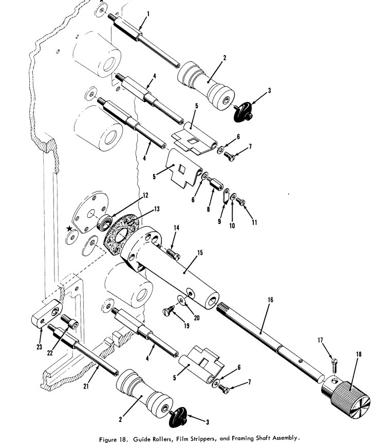
There is some adjustment that can be made to at least one of those rollers below the intermittent sprocket and there is not an actual standard position for it. Just what works. See part number 22 & 23 in the included drawing which allows pivoting of the roller.
Powered by Infopop Corporation
UBB.classicTM
6.3.1.2