This is topic Change over and CP650 momentary button in forum Film Handlers' Forum at Film-Tech Forum ARCHIVE.
To visit this topic, use this URL:
https://ft-forum.com/ft/cgi-bin/ubb/ultimatebb.cgi?ubb=get_topic;f=1;t=012519
Posted by Anhtu Vu (Member # 7689) on 12-22-2019, 03:27 PM:
I need to install a momentary button for my 2 x 35 mm projector set up in order to control the Change Over and CP650.
I was recommended two different methods.
#1:
MOM DPDT button
#2
MOM SPST button connected to a DPST relay
Technician who suggested method #2 said using relay will prevent any damages to my CP650 vs method #1 where I can fry the CP (120v coming from C/O) by soldering the wrong pin or a faulty MOM.
Personally, I don’t see any safety differences between the two methods other than the added relay.
Any suggestions?
Posted by Allan Lyman (Member # 9449) on 12-23-2019, 02:41 AM:
As long as the switch is not connected to anything else,there is no problem with solution one.
please note,the switch has to be on all time,you want to run projector 2.and also with the motor running signal,on both projectors.
alan
Posted by Steve Guttag (Member # 268) on 12-23-2019, 07:10 AM:
You should note that the CP650 is a low-current device and the button/switch you are considering will need to be able to withstand the arcing induced from the changeover on its contacts. Generally, switches are made with higher-current contacts or lower-current ones and they often will have minimum as well as maximum ratings.
I suspect that while you can use a DPST (or DPDT) switch/button...over time, the reliability of the changeover on the CP650 will degrade over time as the switch/button contacts oxidize and refuse to pass the low-current signal.
Posted by Marcel Birgelen (Member # 6801) on 12-24-2019, 01:17 AM:
I would prefer the relay option as indeed, the contacts on the DPST/DPDT switch will probably oxidize and you can get a problem with the low current signal passing thru.
Also, it adds a little extra layer of isolation between the "high" and "low" current on the wiring end. It's probably more a gut feeling than something I can back up with sufficient empirical evidence, but I don't really like high and low current going through the same physically actuated device, you never know how good the isolation is inside those switches.
Also, relays are sufficiently cheap, designed for the task and the minor delay it will add in this case shouldn't really be a problem.
Posted by Randy Stankey (Member # 64) on 12-24-2019, 12:31 PM:
quote: Marcel Birgelen
Also, relays are sufficiently cheap, designed for the task
That's what I think. A relay is designed to be held closed (or in a given state) for an indefinite period of time where a switch isn't necessarily so.
Also, if the relay is properly socketed, repairs can be much simpler; especially in a pinch. Simply pull out the old, bad relay and insert a new spare.
Posted by Jim Cassedy (Member # 4115) on 12-24-2019, 12:38 PM:
I've always preferred to have separate buttons for picture & sound change-overs,
since there are actually times when you don't want them to happen at the same time.
That also solves the risk of somehow getting 110 (or 220)V into the processor.
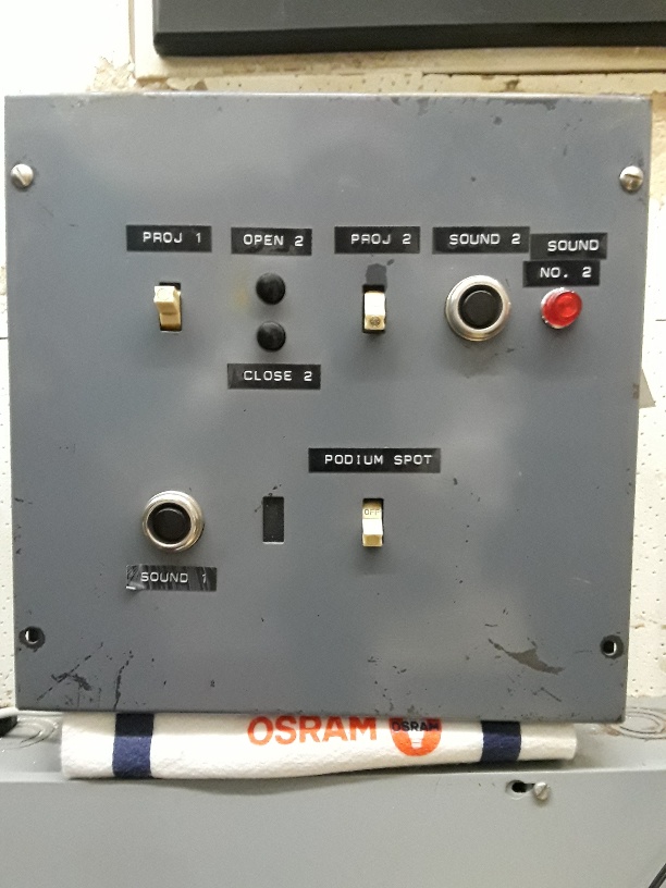
Earlier this year, I re-wired a booth with an old Simplex sound system that had more
or less been taken out of service when they put the digital system in. I wanted to use
the original wall panels which not only had independent picture & sound change-over
capability, but had complete 'dual controls' duplicated next to each projector, & good,
old fashioned pilot lights to see which projector was actively connected to the processor.
I was able to make some wiring changes & re-use the original sound change-over relays,
which were formerly used to switch the exciter lamp current. On the CP-650, shorting pins
1&5 on the 9pin motor start connector forces the processor to switch to projector #2.
Un-shorting them makes it revert back to projector #1.
I re-wired the original relay contacts to do this & it's been working great. (Note- at this
location, I do not have Dolby Digital, only SR & a DTS 6D, which hasn't been used in years)
THIS IS THE PANEL BY PROJ #2. THE PANEL BY PROJ#1 IS IDENTICAL EXCEPT
THAT THE POSITION OF THE SWITCHES & BUTTONS FOR THE PROJECTORS
ARE REVERSED SO YOU ARE ALWAYS MAKING THE SAME HAND MOTIONS
FOR CHANGEOVERS NO MATTER WHICH MACHINE YOU ARE WORKING AT
Posted by Sam D. Chavez (Member # 1841) on 12-24-2019, 02:27 PM:
Is this the Balboa? Looks way better than I recalled. Must be someplace else.
Posted by Scott Norwood (Member # 30) on 12-24-2019, 02:43 PM:
Agreed with Jim. I like having separate controls. My perferred configuration is foot pedals for picture c/o and push buttons for sound.
That is an interesting panel. I have never seen anything like it. What could possibly be the use of being able to control projector 1's motor from the projector 2 panel, though? The only way that I could see this making any sense would be if the projectors had automatic dousers (which I have only seen on Kinoton equipment).
With older Dolby processors, you need a latching relay for the sound c/o. With the CP650, you can use pulsed contacts, so a simple push button on each projector will work (plus the motor-start relays if using SRD).
Posted by Sam D. Chavez (Member # 1841) on 12-25-2019, 12:48 PM:
It was customary around these parts to have duplicate controls at station 1 or 2. You might wish to start #2 projector from #1 position. The foot douser never was a thing here and back in the day you could open the lamp douser from either side.
Powered by Infopop Corporation
UBB.classicTM
6.3.1.2