This is topic DIY PERSPECTA SOUND INTEGRATOR in forum The Afterlife at Film-Tech Forum ARCHIVE.
To visit this topic, use this URL:
https://ft-forum.com/ft/cgi-bin/ubb/ultimatebb.cgi?ubb=get_topic;f=12;t=001103
Posted by Mikael Christensen (Member # 9089) on 10-13-2015, 02:43 PM:
Hi
I hope it is the right place to post this:
I am building a Perspecta Integrator, using the diagrams from Widescreen Museum web page .
My problem is I don't have diagrams for the filters, can anyone please help. ![[beer]](graemlins/beer.gif)
Posted by Mikael Christensen (Member # 9089) on 10-15-2015, 02:29 PM:
Yes.............
Posted by David Buckley (Member # 2600) on 10-15-2015, 02:34 PM:
Is it that you actually want to build one of these things for shits and giggles, or do you actually want to do Perspecta audio and have some media suitably encoded and you'd like to hear it as it is intended to be?
If its the latter, then I'd find a PC, get a multi-output sound card, download Pure Data [link], and build the functions in software. Even learning PD from scratch, it'll still be a lot quicker than assembling a clone of a piece of history.
Posted by Mikael Christensen (Member # 9089) on 10-15-2015, 03:17 PM:
Yes this is serious business, I don't build anything for shits and giggles ![[Smile]](smile.gif) .
.
I have a collection of tube-amps. used in cinemas from 1936 to multi channel racks from 1962, all working and used on weekly basis.
So building one from scratch, is going to be a nice winter project.
Posted by Mark Gulbrandsen (Member # 72) on 10-15-2015, 03:50 PM:
There exists a Perspecta Sound plug in card that goes in place of the Dolby CAT 150 in any Dolby processor that utilizes that card. It was made in Great Britian but I don't know by whom. It shouldn't be impossible to figure out either way. You just need frequency and level sensitive VCA's and opamps and it should work quite well.
Mark
Posted by Steve Guttag (Member # 268) on 10-16-2015, 06:07 PM:
The PAS-1 card. I bought one. Worked well. It is on loan to the AFI/Silver for whenever they happen upon a Perspecta print.
From their sales flyer of years gone by:
quote:
The construction of the PAS -1 is a double-sided PCB with the
same profile as a Dolby Cat150 matrix board, which it replaces
when a Perspecta film is being played. Consequently it will fit
into any Dolby Processor containing a Cat150.
The Perspecta system worked by using
sub audible switching tones buried in
the soundtrack, which when replayed in
the cinema moved the signal to left,
centre, or right stage loud speakers.
The PAS-1 card uses standard
analogue components with mostly TL
074 opamps in the speed filters (30Hz
for left, 35Hz for centre, and 40Hz for
right) and LMI 3700 transconductance
amplifiers in the VCA stages.
Most projectors today run at 24 frames per second and the card
is set for this speed. However the filters can be retuned should
25 f.p.s.or any other speed be required.
Posted by Mikael Christensen (Member # 9089) on 10-18-2015, 12:07 PM:
Thanks for the suggestions, but I prefer to go tubes all the way.
Posted by David Buckley (Member # 2600) on 10-18-2015, 06:10 PM:
quote:
Yes this is serious business, I don't build anything for shits and giggles. I have a collection of tube-amps, used in cinemas from 1936 to multi channel racks from 1962, all working and used on weekly basis.
Respect.
I've had a look at the diagrams, and yes, no detail for the filter assemblies, but they clearly use quite large inductors due to the frequencies involved, and they are noticeably big in the photos. One unusual feature is that the first "row" of three are all in series with the plate of V2, so the input of the filter must be an inductor. The input filter of V1 gives an indication of how the filters were constructed, though obviously this is the high pass version rather than the bandpass filters necessary for each channel.
I suspect you'll have to design and build from scratch, Horowitz and Hill being the obvious place to start, and/or try and find an old version of the ARRL handbook, they had information on building audio filters in the valve era.
Posted by Mark Gulbrandsen (Member # 72) on 10-19-2015, 04:03 PM:
Good luck having those bandpass filters wound and properly tuned. The only tube Perspecta unit I ever heard work correctly was at Dick Prathers house in Portland and it only worked because it was taken to the Tektronix factory where they had proper spectrum analyzers to look at the center frequency and slopes of the existing bandpass filters. They had to melt the wax out of the tops of the coils to access the tuning capacitors and adjust the tuning of each bandpass by selecting new capacitors of the proper values.
Yes, it was impressive! But the Solid State version would likely work even better.
Mark
Posted by Mikael Christensen (Member # 9089) on 10-20-2015, 11:47 AM:
Yes I know is is going to be a challenge, but that doesn't scare me ![[Big Grin]](biggrin.gif) .
.
I might compromise, and use filters with ICs.
Posted by Mark Gulbrandsen (Member # 72) on 10-20-2015, 03:53 PM:
That would make it a whole lot easier...
Posted by Robert Furmanek (Member # 7026) on 11-23-2015, 01:28 PM:
I had a 1954 Fairchild integrator that was restored by Bob Eberenz, Robert Fine's right-hand man. It sounded fabulous and the panning/gain control worked beautifully.
Posted by Gordon McLeod (Member # 33) on 11-23-2015, 01:46 PM:
Dion Hansen ex Dolby labs made the solid state unit that replaced the cat 150 cartd it is impressive Also Chase Audio in the US made a card as well
Posted by Robert Furmanek (Member # 7026) on 11-23-2015, 04:29 PM:
Wasn't one of the cards lacking the gain control feature on the 3 channels? That's a very important aspect of the system.
Posted by Mikael Christensen (Member # 9089) on 09-25-2016, 12:38 PM:
Hi again
How time flies :-), due to busy work schedule.
My Perspecta project was not going so fast, but now I am back with full speed.
I have made a test setup with tubes and IC's in the filter section, and it works so so.......
Overall problem is I need to find out what's inside filter boxes !
There has to be somebody out there, who has some info. about this matter ?
Posted by Mark Gulbrandsen (Member # 72) on 09-26-2016, 02:52 PM:
I don't have any info of the exact nature of the insides of the boxes not do I remember that the patent has any info. I can tell you that it is a tuned resonant deal of some sort, possibly a tank circuit that affects the bias on the stage after it thus controlling gain. A friend in Portland had a working Perspecta unit that he recapped but still wouldn't work properly and it turned out that those tuned resonant tank circuits had capacitors inside the tops of the cans that had drifted. So it is some sort of RC tuned LF band pass circuit. His father in law who happened to be an engineer at Tektronix at the time melted the wax out of the transformers and took the guts and put them on a spectrum analyzer. Then he put in new caps to tune each band pass filter back to its center frequency again. Then resealed them back in the cans in the original wax again. The results were spectacular.
So making these filters will take some ingenuity on your part to either duplicate what they originally used, or to engineer something else that does the equivalent job at 30,35, and 40 hz.
It might be sort of a brick wall problem and was no doubt why others did this in Solid State.
Mark
Posted by Mikael Christensen (Member # 9089) on 09-27-2016, 01:07 PM:
Hi
Thanks for the reply :-)
My theory is that the first "filter" A, is the bandpass filter.
and the second B is some sort of transformer coupled driver stage,
for the 6AL5 tube, due to the fact that there is a negative voltage of -20V.
http://i283.photobucket.com/albums/kk294/dfmsbofa/ft1.jpg
Posted by Mark Gulbrandsen (Member # 72) on 09-28-2016, 10:14 AM:
I believe that A is a low pass filter and that there are three of B, one for left, Center and Right. Or one B for each frequency. Filter A would cut off all frequency just above the highest control frequency of 40 hz. Filter B's output feeds the 6AL5 dual diode which rectifies the AC voltage output from the B filter and the resulting DC voltage is used to control the gain and phase of main audio stage for that channel.
You can see from the following schematic (204 and 208) what is inside those eight band pass filters on these units. They would be quite difficult to produce and very expensive because they are going to have to be custom made and tuned. 208 is a high pass filter by the way. These units are VERY simple with the exception of these RCL filters.
I spent about ten minutes on line looking for a company that can manufacture low frequency band pass filters to no avail. You might want to contact a company like Lundahl Transformers in Sweden to see if they might be of any assistance. They make the best audio transformers on the planet! They are also a small enough company that they might be interested in making something like this. You are gonig to need to kow the original specs of the filters as designed though. They were very steep filters. http://www.lundahl.se/
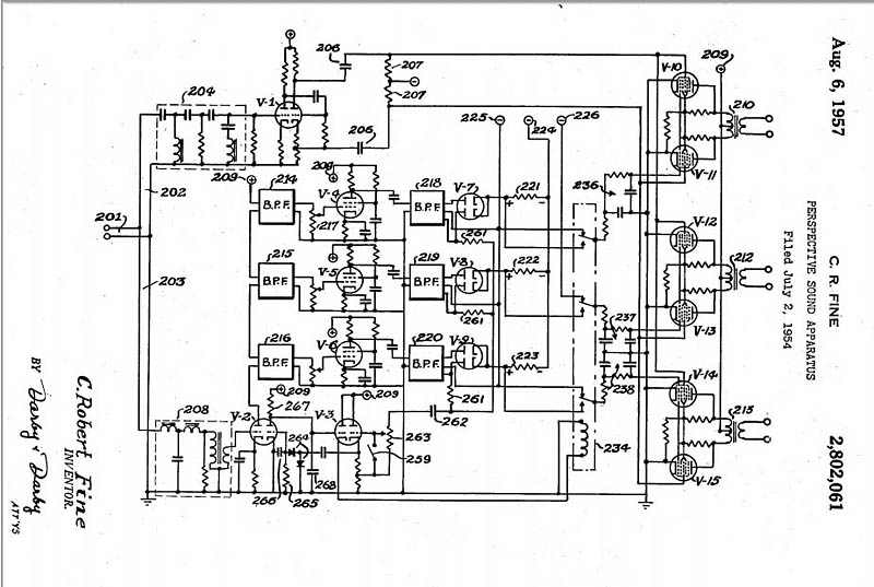
If I were going to do this today I'd do it all with Digital DSP. It would actually be easier to do and no filters involved because it would all be done in the digital domain.
Mark
Powered by Infopop Corporation
UBB.classicTM
6.3.1.2