This is topic Digital Cinema Network Diagrams in forum Digital Cinema Forum at Film-Tech Forum ARCHIVE.
To visit this topic, use this URL:
https://ft-forum.com/ft/cgi-bin/ubb/ultimatebb.cgi?ubb=get_topic;f=16;t=001591
Posted by J-sun Bailey (Member # 2811) on 08-07-2013, 01:36 PM:
Is anyone out there willing to share a Digital Cinema Network Diagram? I'm trying to see the best way to setup our Network for being able to transfer content between projectors.
Thanks.
Posted by Justin Hamaker (Member # 2165) on 08-07-2013, 05:58 PM:
I don't have a diagram, but I'll give you a brief rundown on how my booth is configured.
We have Cinedigm LMS, 5 NEC2000C projectors, 5 GDC SX2001 servers, 5 Dolby CP750, 5 Christie ACT automation.
Subnet mask is 255.255.254.0
LMS is XXX.XX4.XX4.25
Service laptops: XXX.XX4.XX4.16-20
The X in the last octet is the auditorium number. If you have more than 10 auditoriums, you would change the last 2 numbers accordingly.
GDC servers management: XXX.XX4.XX4.11X
GDC servers content: XXX.XX5.XX4.11X
Projectors: XXX.XX4.XX4.19X
CP750: XXX.XX4.XX5.3X
ACT: XXX.XX4.XX4.3X
Network cabling
Each projector has 3 x CAT6 home run to a patch panel at the LMS.
-1 for GDC Server Content
-1 for projector switch
-1 redundant back-up (just because it was easy to pull an extra cable at installation)
Each projector switch has the following connections
-GDC Management
-GDC Security Manager
-Projector
-ACT
-CP750
-Home run to LMS patch panel
This configuration allows me to communicate with any device on the network from any point in the network - including my office computer, which uses one of the service laptop IPs.
As far as I know, there is nothing in the GDC interface which allows me to transfer content between players. However, the Cinedigm LMS/TCC software has a function which allows you to transfer between players (but not from players to LMS).
My understanding is some integrators are now going with different IP scheme which puts each auditorium on it's own subnet (something like 255.255.255.240) to keep devices from talking outside the auditorium. In this scheme, all devices would fall within a range of 16 ip addresses (ie 192.168.0.240-192.168.0.255). I'm not sure how this affects transferring content between players. I believe you could still access any device from any point in the booth (as connected above) if you have your service laptop subnet mask set to 255.255.255.0.
Posted by Dave Macaulay (Member # 813) on 08-10-2013, 10:54 AM:
Again, no diagram... sorry.
How many screens do you have? For a small site (maybe up to 5 screens?) you may get by without a dedicated media network. The management network gets rather busy when transfers are happening and the traffic between server and projector can get lost especially with simple "home network" switches, causing various problems.
You really need a 1 gb/s network - CAT6 cabling and gigabit ethernet switches for the media transfers. With a 100mb/s network the transfers are super slow but with 1gb/s they are 3-4 times faster than USB. If your screen management networks are set up with 100mb/s switches then adding a media network will be cheaper since you won't have to replace all the local switches.
You need one central switch with enough ports to connect all the servers to (plus at least one extra for connecting a tech computer to), and cabling from each server to that switch.
It's preferable to have a separate media network so let's assume you have one. Each screen's local management network can be unchanged that way, just in case the installer set them up all identical - ie all with the same component addresses such as server at 192.169.100.1, projector on 192.169.100.2, etc.
You will have to set up the second ethernet ports on each server: they must be on a different subnet than the management (one or all of the first three sets of numbers must be difference if your netmask is 255.255.255.0, the port should refuse to do the setup if you try to have it on the same network segment as another port).
Try something like 10.120.1.xxx. The netmask can be 255.255.255.0 for simplicity. Set each server's address by screen number... screen 1 server could be 10.120.1.11, screen 2 10.120.1.12 etc.
Connect the cabling once all server IP addresses have been set. Use the correct server port - this depends on server type, they all have a network port for a media network though. Dolby servers assign the port and device addresses and netmasks during initial configuration - it's easier to just use their scheme than to change it to something else. Their default addressing setup is in the installation manual.
You can check connectivity by opening a server terminal window and using "ping 10.120.1."xx" to each other server - or have a computer connected to the media switch with its port set to a non-server address in the same network segment and its netmask matching the servers', and ping from it to all servers.
Now you have to set up each server to easily download content from the other servers: pushing content from one to another is possible but usually much more complex (a terminal task using ftp). With Doremi you set up the servers in a control panel application. Once they are set up, you just open "ingest manager" and clicking on the box "local content" pulls down a list of all the servers you have set up, click on one and all its content is displayed. You can also configure the ingest servers to allow playlist ingest, but the server will not check if content in a playlist is actually present - when showing the playlist it will just ignore any missing content.
The various TMS/LMS systems have all network addresses assigned by the associated NOC so the TMS/LMS doesn't conflict with other sites on the NOC. The schemes they use assign addresses for all possible network devices a theatre could have - automations, sound devices, projectors, servers, advertising players... so their network schemes are way complicated. There's no need to use one so thoroughly compatible in a cinema without a TMS/LMS.
Posted by Jim Cassedy (Member # 4115) on 08-10-2013, 04:12 PM:
The above explainations are waaaay too complicated & confusing.
It's best to keep it simple.
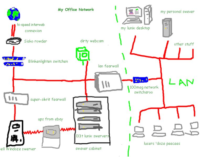
I built my network using this diagaram I found online. I just added a mucks to the
"Other Stuff" part of the LAN and connectified up my digitalized cinemer serva & projectorthingy.
If you do it right you won't have to mess with any submarine net masks & othercraplikethat. ![[Smile]](smile.gif)
Posted by J-sun Bailey (Member # 2811) on 08-11-2013, 08:26 AM:
Thanks everyone for your input, here is a current diagram of how we're setup:
We don't have separate management/content networks.
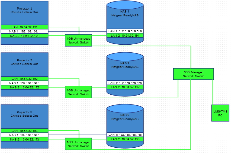
The direct connection from the projector to the NAS device on the 192.168 network was setup by our installers; the other way that I see of doing it would be to team the two network ports on the NAS to use the same 10.64.32 address thus giving 2GB of throughput.
Posted by Dave Macaulay (Member # 813) on 08-11-2013, 09:10 AM:
OK, Solaria 1 ... I suggest you call Christie tech support and ask for help. This is a very different setup from any other projector/server system. You need specific instructions to avoid screwing up the server-NAS connections. I assume that transfers will have to be between the NAS boxes over the management network, I have no clue how to tell one to send content to another.
Powered by Infopop Corporation
UBB.classicTM
6.3.1.2