This is topic Use GPO and relay on Showvault in forum Digital Cinema Forum at Film-Tech Forum ARCHIVE.
To visit this topic, use this URL:
https://ft-forum.com/ft/cgi-bin/ubb/ultimatebb.cgi?ubb=get_topic;f=16;t=003589
Posted by Biraj Thakuri (Member # 10203) on 02-12-2019, 09:04 AM:
Hello all,
I am having a bit of an issue trying to work with GPO and relay. I have an series 2 Christie projector with Doremi Showvault and IMB. I am trying to have an automated lighting system on our theatre by using the macros.
We have only manual light switches so GPO may be the best option for that.
I have an 5v 8 relay and am trying to connect it to the GPO section of the IMB.
I have made everything ready with showvault field installer as well as IMS field installer. The confusion is which wire should be connected to where.
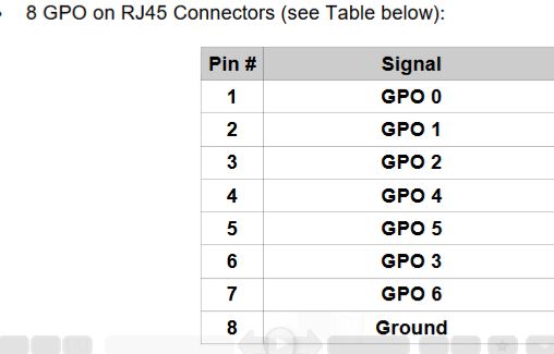
From the Showvault manual:
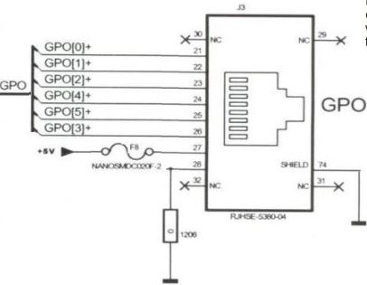
From IMS manual:
The GPIO pins in relay:
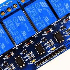
As you can see they are very much different.
I understand that the ground from GPO goes to ground on relay and then I am confused about the rest of the wiring.
For e.g - 1.Does the IMB GPO output 5V and from where?
2.There is mention of 5V on IMS manual but not on showvault manual
3.Pin no. 1 to 7 gives out signal then from where should the relay get power.
Showvault manual has no mention of 5V anywhere.I wanted to ask here before trying anything on the valuable server.
Thank You for the help.
Posted by Harold Hallikainen (Member # 5405) on 02-12-2019, 09:46 AM:
I suspect these are open collector or open drain outputs. They are similar to switch closures to ground. If your relays have polarized coils (some do because of permanent magnets in the relay), connect the positive side of the relay coil to the +5VDC output of the server. If the relay coil is not polarized, connect either side of the relay coil to +5 VDC. Connect a diode across the relay coil with the cathode (the side with band) to +5VDC. The diode allows the relay current to continue flowing as the magnetic field collapses and prevents generation of high voltage that could damage the server output. Connect the other side of the relay (the "low side") to the GPO output of the server. When a GPO is activated, it acts like a switch to ground which then allows current to go through the relay.
Check the current rating of the GPO outputs and the relay coil. Make sure the GPO output current rating is higher than the relay coil current to avoid damaging the GPO output.
Good luck!
Harold
Posted by Carsten Kurz (Member # 5396) on 02-12-2019, 09:49 AM:
The IMS Manual also shows an example for direct relay control by the GPO. See 'Typical application'. It works the same as with your relay board - the GPO switches an externally supplied switch voltage through into GND. As the IMS GPIO does not support that switching voltage, it has to be sourced externally, e.g. by using a 5V USB power supply/charger.
http://www.film-tech.com/cgi-bin/ubb/f16/t003410/p1.html
Harold - the relay board shown uses it's own optocoupler and transistor relay switch per channel, so, pretty safe.
Here's the description and schematics:
http://wiki.sunfounder.cc/index.php?title=8_Channel_5V_Relay_Module
That article doesn't mention that there is a separation jumper that can split input stage supply from coil switching supply (it's shown in the schematics, though). So one could supply the input stage switching circuit from a low current supply, and the coil from a suitable other higher current capable supply. In the case of the early revisions IMB GPO, there is no supply voltage available to supply the input stage, so, one would use the same 5V supply for both input and coil switching.
There are two different revisions of the Showvault/IMB GPOs - early ones offers 7 GPOs (0-6) + GND, but no 5V supply voltage (8Pin RJ45 only), the later revisions offer 6 GPOs (GPO6 unavailable), GND, and a +5V/200mA supply on pin 7 (which carries GPO6 in earlier board revisions). Doremi has a technote describing these differences (IMB.TB.005120.DRM).
- Carsten
Posted by Biraj Thakuri (Member # 10203) on 02-13-2019, 12:12 AM:
Thank You very much for the information Harold and Carsten.
I had read about the jumper that separates the input supply from the relay so will definitely do that once I sort this out.
So as I have the Rev E (later) IMB board, that means we get only 6 GPOs, 5v output from pin #6 and ground from pin 8# totaling to 8 pins on RJ45.
So external power to relay is not necessary. As mentioned my Carsten I have to split the power and provide it to the coil switching mechanism.
And can you point me out to the technote you mentioned (IMB.TB.005120.DRM), I didn't find it. Thank you.
Posted by Marcel Birgelen (Member # 6801) on 02-13-2019, 03:04 AM:
Since the coil switching circuit is optically isolated from the stage circuit and according to the schematics, does have its own ground, I would invest the handful of dollars for a separate 5V power supply for the coil switching supply.
Firstly, I would not trust the 5V supply in my server to be sufficient to drive 6 coils simultaneously in the worst case, even though those relays look flimsy enough... And secondly, if something in that circuit would fail or overload, I'd rather have blown up my $5 power supply than the GPIO port of my server.
Posted by Carsten Kurz (Member # 5396) on 02-13-2019, 06:30 AM:
Yikes, I thought I made that clear - you need a separate supply for the coil switching. 200mA from the IMB is too risky. You may feed the input stage from it, but then use a USB-wall charger or similar for the coil switching. I would recommend a USB wall charger, since they can easily be replaced in case of a defect. Just use an ordinary cut-through USB-A cable towards the relay board/enclosure.
I just sent you the doremi GPO technote by mail.
- Carsten
Posted by Biraj Thakuri (Member # 10203) on 02-17-2019, 09:11 AM:
Thank you very much Marcel and Carsten for clarifying the confusion. I have the relay ready and am planning to try it out tomorrow.
Will definitely use the usb charger for coil switching. Much less risk.
I have one question though. Which one of the following setup will be better and safer?
1. Direct GPO to relay (my current setup)
2. RS232 to Adruino and then relay
3. Ethernet to Adruino and then Relay
Thanks again and please clarify my above question. I wanted to do this at minimum risk to the IMB.
Posted by Carsten Kurz (Member # 5396) on 02-17-2019, 10:14 AM:
If you are programming the Arduino yourself, the effort needed to make it robust is clearly higher. The direkt GPO to relay in comparison is simple. Given that you have two serial levels of optical isolation, the risc is very small.
People usually choose the serial or ethernet based approach if they want to have additional functionality - e.g. an Arduino in between could be controlled by multiple masters, or implement higher level actions (e.g. automatic pulse sequencing). If all you want to do is control lights and curtains from a ShowVault SPL, the direkt GPO approach should be the easiest and safest. If you later feel you want more options, you can still add an Arduino, or buy a JNIOR.
- Carsten
Posted by Marcel Birgelen (Member # 6801) on 02-17-2019, 10:22 AM:
If you use a separate power supply for your coil switching, I don't see a real risk for your IMB. Since your stage switching will have a common ground with the GPIO, I guess it will be best if you power them from the IMB itself.
The most secure solution for the IMB would obviously be the Ethernet -> Arduino -> Relay board -> Relays route, because your IMB is already connected to Ethernet, you're not hooking anything else up to your IMB. But still, do you need the complexity of this setup? If you want to switch more than 6 separate relays for example, this could be a route of doing so. If not, then the first solution should be good enough.
The RS232 route is much like the Ethernet solution, only that you're now hooking up the Arduino directly to the RS232 port, which would be just a tiny bit riskier than taking the Ethernet route.
PS: It looks like Carsten and I hit on the Submit button almost simultaneously. ![[Wink]](wink.gif)
Posted by Ioannis Syrogiannis (Member # 3235) on 02-17-2019, 04:21 PM:
I would prefer to use an extra layer of complexity (Arduino), whatever that may mean in order to not have the lighting system status depending on the continuous GPO power output coming from the IMB.
If I am not mistaken, in order for the circuits to be in a condition other than normal (Normal Open/Close depending on how they are connected) the pins in relay should be continuously powered. They don’t work with pulses.
During and between sessions, I find it a bit more probable to be obliged to restart the projector or/and IMB than an independently powered Arduino.
On the other hand, if it was me, I wouldn’t trust those relays to be in charge of a theater’s lighting system either. In a venue where security is considered to such a degree as it is in a cinema, a more reliable investment is in order and the whole discussion here would better be a proof of concept and a way to better get acquainted with the equipment.
Posted by Marcel Birgelen (Member # 6801) on 02-17-2019, 05:03 PM:
It depends on what you want to do.
I'd not trust those flaky looking relays to directly drive the lightning of my theater, even though they're rated at 10A 250V.
But there is nothing wrong with them sending pulses to some latching relays for example. You know, those somewhat beefier DIN-rail mounted ones, from a recognizable and somewhat trustworthy brand.
Those latching relays could have different inputs as well, such as simple push-buttons inside the theater or booth.
Although, my preferred solution in such case would be to ditch those first row of relays entirely and just use a bunch of opto-couplers to drive the big relays directly, to simply avoid delays and sticky relays.
Posted by Biraj Thakuri (Member # 10203) on 02-22-2019, 09:29 PM:
Thank you Marcel, Ioannis and Carsten for your valuable suggestions. I appreciated it a lot.
I will definitely get a better relay for the use and will try with Arduino in between.
And Carsten, I couldn't find details about which revision my IMB board is. I have recently updated to 2.8.20 and got the following image from the webUI.
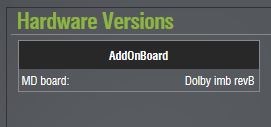
Can't differentiate if it is the earlier revision or later revision.
Thank you.
Posted by Carsten Kurz (Member # 5396) on 02-23-2019, 06:35 AM:
Biraj - I sent you the Doremi Technote on IMB revision/GPO changes. It looks as if your IMB is a revB. Whatever the revision is, you should be able to measure the existence of the 5V supply on the GPO port. Even if the 5V is missing, you can use that relay board if supply the input stage with 5V (the same as the coil switching).
However, if you are not able to measure and make your own conclusions, you should probably not mess with your own hardware additions to an expensive piece of gear.
Regards - Carsten
Posted by Marlon Martins (Member # 8823) on 02-25-2019, 07:27 AM:
i got also a automated "light system" with those boards.
using in a showvault and alchemy servers.
as mentioned, those relays are not so powerful, do not connect high power light. one relay in my system failed, but after replacement, works fine for over 2 years i think
if i recall, the connection was simple, ground and 1 pin for each gpo, directly on the inputs of the board.
but the alchemy server has separated grounds, so, just need to join them
one tip i have, is i decided to use the relays as a "turn off" system, so, the lights are on by default, and the system turn off the lights. it's better in case of any problem with the device, power outage, etc.
Posted by Biraj Thakuri (Member # 10203) on 03-20-2019, 06:22 AM:
Thank you for the reply Carsten and Marlon.
Yes, it was a surprise for me that the IMB is a rev B as the back side of showvault sticker has Rev E ![[Confused]](confused.gif) and I couldn't find any GPO information regarding it.
and I couldn't find any GPO information regarding it.
From your information I am very clear regarding the wiring to be done. But I just can't find what I am looking.
For e.g I couldn't find ground in the GPO
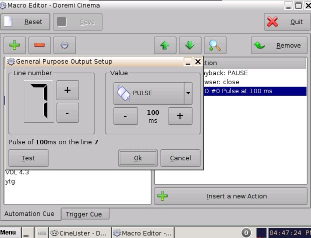
The RJ-45 has 8 pins so the I got 0-7 pin no. as in the screenshot above.
I have searched the field installer manual but all of them mentioned Rev C and Rev E only. No Rev B.
Rev C: 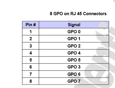
Rev E: 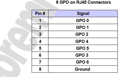
And Marlon can you please explain me the whole circuit of the automated light system and how you connected the GPOs to the relay board and its working.
Thank you for helping me guys.
Posted by Carsten Kurz (Member # 5396) on 03-25-2019, 09:38 AM:
You don't need to find GND in a GPO. If at all, it is available on a (shielded) connector shell, forwarded to the cable screen.
But for an optoisolated GPO to work, GND is not necessary. Get a multimeter or continuity tester and just measure resistance/continuity accross two adjacent pins. You could e.g. setup an autorepeating SPL, setting all GPOs up after another, the check continuity while playing that playlist.
Someone once mentioned on this forum that on some Doremi IMBs, the GPOs wouldn't work at all, possibly due to missing parts. I don't know wether that's true, or wether it's just a false impression caused by many different wiring versions without a clear scheme to find the right one. However, with a continuity or resistance meter, you should be able to find out quickly what's going on.
- Carsten
Posted by Biraj Thakuri (Member # 10203) on 04-20-2019, 08:29 AM:
Thank you for the clarification Carsten.
Will definitely give it a try. Will keep the thread updated.
Powered by Infopop Corporation
UBB.classicTM
6.3.1.2