This is topic Valve amp designs in forum Film-Yak at Film-Tech Forum ARCHIVE.
To visit this topic, use this URL:
https://ft-forum.com/ft/cgi-bin/ubb/ultimatebb.cgi?ubb=get_topic;f=8;t=004218
Posted by Paul Trimboli (Member # 1509) on 08-23-2005, 09:09 AM:
I hope this is the correct place for this. Not sure if it should go in the afterlife...will find out soon I guess!
I am wanting to start building my first valve amp. As a first project I would like something around the 20watt mark, and do it cheap! I have found this website that uses a 100volt impedance matching transformer as the output tran. http://www.alphalink.com.au/~cambie...lls_6CM5amp.htm
I would like to do something similar but I want to use valves that I have avaliable from local electronics shops. As stated in the website the transformer is 8k:8ohm.The valves I have avaliable are 12AX7, EL34 and 6L6. I assume the design would be Push Pull. Anyone have any simple designs or know of a good link? I have had a bit of a look around diyaudio.com but can't find what I want. I have posted on there also but thought there might be someone on here who could help! ![[thumbsup]](graemlins/thumbsup.gif)
Posted by David Buckley (Member # 2600) on 08-23-2005, 05:37 PM:
A pair of EL34s will easily produce 20W, most 50W guitar amps use a pair.
As I think you've sussed, the difficult part to get hold of will be the output transformer, you need to start raiding junkyards and stuff.
A couple of secs with google found http://www.beamecho.mcmail.com/rebuild.htm, which looks a pretty typical schematic for an ultra-linear push pull valve amp, he says, not having looked at something like this for many years...
12AX7 is the same as an ECC83 as used in the link I've posted.
I'd recommend you use a solid state power supply, rather than an old double diode valve. Also, you dont need initially to get all the way back to milivolts with valve gain, you can start with a phase splitter and a couple of output bottles and drive it from your hifi preamp, get that going, then think about if you want to have the small signal stages valved.
Good luck!
(Note to mods - yes I know about the link rule, but I'm bending it on this occasion as the link is to an example of the genre, replaceable with many others)
Posted by Mark Gulbrandsen (Member # 72) on 08-23-2005, 08:37 PM:
Really the best place to go Paul is www.diyaudio.com There are more tube guys there than apes in the jungle and many good designs. I might also suggest that you take a very close look at the Pass Labs single ended MOSFET stuff while you're there. The Mini-Aleph is a 15 watt per channel single ended pure class A amp that is very inexpensive to build, super durable, and sounds ALOT better than the tube amp you would be building. Parts are also inexpensive and readily available.
Mini Aleph Thread
Mark
Posted by Luciano Brigite (Member # 1104) on 09-24-2005, 07:56 PM:
Ha! I don't know I missed this topic.. ![[Embarrassed]](redface.gif)
You can get 20W out of a pair with EL34 with low distortion somewhat easily,however the output transformer is 6600Ohm primary with taps for screen grid connection at 43% of primary turns and 4-8-16 ohm secondary.the distortion stated on the tech data is of about 0,8% at maximum signal. hte same configuration with a little more input will put out 37W with 1,3% distortion.
The phase splitter is made with a ECC83 (12AX7).
Most of the data sheets for tubes will have one or other suggestion for the tube, some also has a circuit diagram along with a table with component values to experiment.
6L6GC can also be used with the same output transformer (6600 ohm with taps)voltage ,currents and component values are a little different than the ones for a EL34 circuit.6L6 also can be used in Push Pull A class where it'll put out about 15W.
There are also single ended circuits, all in class A using only one output tube. distortion however is higher, reaching the 10% sometimes more,but is easier to do and costs less, hte only expensive part being the transformers.
I made a few valve amps for myself, all of them single ended.one of them uses 2 ECL82 wich has the pre and output in one valve and uses not more htan 7 external components for each channel and a power supply common to both.
If you have more than enough patience.. you'd try what I did,wind the transformers. It takes a lot of time ( since I wound all of them by hand) a bit of math to find out number of turns, core sizes and wires to use. the results will vary a lot. I'm pleased with the last pair I made wich took nearly 3 months to get done.
Maybe it's a good idea start with single ended circuits to get familiar with it then go to push pull. if you can get the 6550 valve at your local shop, it'll give you a SE amp that puts out 12~13W,I'm hopping to finish one with these tubes next month or when time and laziness allows me to finish the transformer winding ![[Big Grin]](biggrin.gif)
Posted by Paul Trimboli (Member # 1509) on 09-24-2005, 09:40 PM:
Hi Luciano
I got some help from some people over at DIY audio to design am amp that uses 2 12AX7s and 2 6L6s per channel going into the 100line matching transformer I wanted to uses with is 8k. I have a couple of web links that might be of some interest to you about winding output transformers, something I would very much like to try! http://galileo.spaceports.com/~fishbake/ot1/ot.htm
Where are these schematic of the amps deigns you were talking about? What have you done for power transformers? I was going to use 2 transformers back to back T1 running normally supply 25VAC to the 30VAC centre tapped secondary winding of T2 which will provide about 150VAC on what is normally the primary winding of T2. This then runs a volatge doubler to give me the HT of 400V. The heaters are run in series from the 25VAC secondary of T1. Hopefully that works out OK.
Posted by Will Kutler (Member # 770) on 09-25-2005, 12:26 PM:
I have the Antique Radio Supply Catalog, and they are Hammond distributors.
Anyhow, Hammond has transformers specifically designed/built for specific tubes. I'm interested in what some of you (Mark G.) think about their products.
I also noticed that Hammond also sells a large variety of ready made sheetmetal chassis. And Chassis hole punches are also available.
And maybe someone like Mark can give a simple rundown about why transformer design is critical to audio sound?
Cheers
K.
Posted by Mark Gulbrandsen (Member # 72) on 09-25-2005, 01:23 PM:
Will,
There are so many factors, some very critical, that determine the quality of an output tranny that one could fill an antire book on it, and I'm not the expert on them to write that book by any means. There is also the "Snake Oil" aspect that does hold true to output tranies and only comes from years of winding them and gathering alot of experience. The very best off the shelf output trannies for push-pull designs that I have used are made by Plitron in Canada and are torodial. The Hammond line is good stuff but more general purpose than not.
I don't mess with tube stuff any more, sold off my last pieces tube gear about 5 years ago. I've built quite a few and owned many high end tube pieces over the years and have still not been as satisfied with tubez as I have been with really good solid state stuff... mainly SE MOSFET type but lately I've been spending ALOT of time on cloning the original Krell KSA-50 MK-2 Class A power amp. I even did a run of 200 pcb's for a group buy of them over at diyaudio.com. This one is pretty hard to beat and was by far the very best amp that Krell ever produced and is still used as a refrence by many reviewers to this day..... Keep in mind that the speakers I use are about 89db sensitivity and none of the smaller SE tube amps can drive them very well... The SE tube stuff is the best of the tube stuff......
I just don't biy high end electronics any longer I always build it myself since I can build it far better than the original factory built unit ever was.... larger trannies, more power supply capacitance as well as CLC or CRC type supplies. and I also run them at alot higher bias levels than the factory versions so they also sound tons better. There are alot of things you can do in home built designs that the factory compromised on in the end product, or that the timeline of production limited such as semiconductor speed, and other overall parts quality. Below is a photo of a prototype channel of the KSA-50 mk-2.
This amp does 50 watts class a and then switches to high bias class AB up to clipping at about 75 watts. It also doubles its output power every time the load impedance is halved... down to 2 ohms. This is someting that the original couldn't do below 4 ohms! There is no current limiting or protection circuitry in the amp at all nor is it needed. Each channels output stage is capable of sinking close to 100 amps and dissipating over 1200 watts so the worst that might happen is a blown line fuse. There are no FETS, all bi-polor semis. Normal dissipation and idle current for one channel is 150 watts and 4 amps.... so things are pretty conservative.
Mark
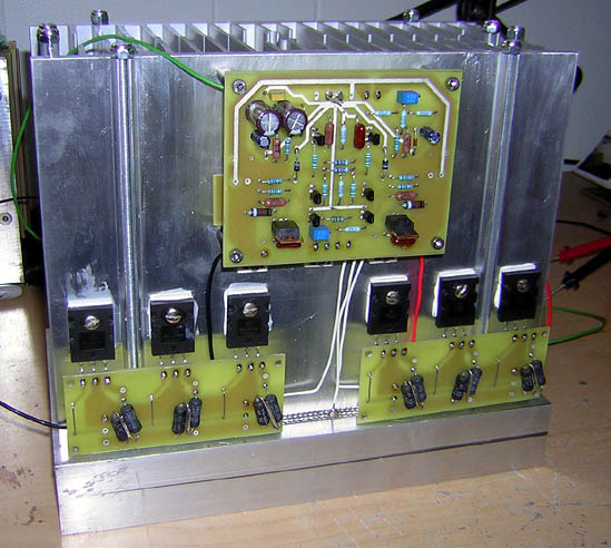
Posted by John McConnel (Member # 2000) on 09-25-2005, 09:59 PM:
Nice looking construction, Mark. And impressive specs.
John Mc.
Posted by Luciano Brigite (Member # 1104) on 09-25-2005, 10:37 PM:
Paul,
I wound all of my transformers, power and outputs, all of them by hand.the power transformer was the first of this kind I made and I'm pleased with it, it takes about 2~3 hours to get hot and some 3 more hours to reach the point where you can't keep your hand in it for more than a few seconds. For the outputs, it's another story.
It took me a few times to come out with something I judged good ( for me) ,a lot of things were changed, from core sizes to winding sequence and wire gauges. the last pair I made have 8 secondaries in parallel and a primary split in 10 parts interleaved (??) with the secondaries. this arrangement was one of the winding methods shown in the radiotron designer's book .
For the circuit it's only described, not drawn, in the data sheet for the EL34 from Mullard. In it the values for the split phase stage are pointed out for two circuits and the voltage,current and plate to plate load are also given. there are other suggestions for different power outputs with teir respective distortion ratio.
I'll draw the schematic for it sometime this week and if time allows, revise the calculus for the output transformer I mentioned for it ( 6600 ohm prim./4-8 ohm sec).
I remember Mark once mentioning that output transformers aren't easy to do,indeed they are not, even the simple, small ones have their tricks,however it didn't make me leave it behind, nor did the first tries I made.Right now I have another circuit on the way, the power transformer is already made and tested ( it came out better than the first I made) and the outputs have started, for these I'll be trying the same arrangement I did for the last outpts I made . I don't have all the gear to test them but while playing with a portable RTA and a cd with test signals, the rta showed a full response when a swap signal was played tru the circuit ( and my ears complained when the swap reached the 2Khz and up, ouch!)
Posted by Will Kutler (Member # 770) on 09-25-2005, 11:11 PM:
Hi Mark
Very nice, clean work! I am curious about your finned case. Did you machine or purchase it?
Unfortunately I do not have the opportunity to listen to much hi-end gear. The last time was at a "big-boys toy show" in the Phoenix area. A local hi-end dealer had a Macintosh display under less than ideal acoustic conditions, but it sounded wonderful! However, while this was a "hi-end" dealer, I was not impressed with their lack of ability in answering technical questions.
Unfortunately, I really dislike going into "hi-end" audio stores. My experiences in both AZ and Southern Ca is that many of these stores are far beyond snobbish and arogant!
But Mark, I am finally in the midst of restoring my 1938 RCA 816K am/shortwave console. I've heard them restored, and they do sound nice! Unfortunately I was not able to get original style cloth covered wire in the needed colors. So, I compromised and am using 600 V rated 18 gage wire in solid colors and marking my own stripes with 3M FP301 Heat Shrink. But at least I am able to use the correct colors and chassis wiring layout. The other compromise is the modern cap and resistor styles, but at least they are all the correct original values and I am able to "stuff" the original top mounted E-Caps to retain original aesthetic appearance.
I'll try and post some pics.
My other piece of "hi-fi" gear is my Harmon-Kardon TA-230, which I believe was the first commerically available AM-FM Stereo Tuner. I had one years ago when I was in the service, but unfortunately had to sell it. I acquired another some time ago while in the clutches of an acute nostaliga attack, and this unit also awaits restoration. With a good set of speakers, these were very nice sounding units, also.
Cheers
K.
Cheers
K.
Posted by Mark Gulbrandsen (Member # 72) on 09-26-2005, 07:57 AM:
Will,
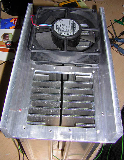
Good luck on your RCA there. That wiring upgrade will make it safe to play it as an every day radio!! I use silver plated-stranded-teflon covered wiring on most of my projects. The amp is not in its case as of yet. Those are two flat back large finned heat sinks that are mounted face to face as an air tunnel. Under that C channel base are two 4" 12 vdc Pabst fans that run on about 4 volts so they are not audible. These fans keep the sink temperature at about 50 deg C. in a 70 deg f. room. Convection cooling ould have required three times that amount of sink per channel to maintain that 50 deg C. temperature. This may seem pretty hot but its only 1/3 of the rating of the devices so theres a very safe margin there as well. There is also a clixon on the end of each sink that shuts down that channel if the temp exceeds 70 deg C.
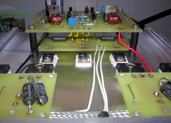
The driver board with bias and driver transistors mounted stacked under the main board. All wiring is kept to just inches in length.
There are "hi-end" stores that are not snobbish and that reminds me of a good story. I once was out to buy a new pair of speakers and literally had 5K in cash in my pocket. Went to a high end store in down town Chicago dressed in my old blue jeans and sneakers.... no one from the store ever asked if there was anything I needed so I left and went to a differnt store in Evanston later that day. There I was immediately taken care of in a very courteous and helpful manner. Several months later that downtown Chicago hi-end store folded!
Mark
Posted by Floyd Justin Newton (Member # 1316) on 09-26-2005, 04:12 PM:
Mark--
Serves 'em right ! ![[fu]](graemlins/fu.gif)
Posted by Luciano Brigite (Member # 1104) on 09-26-2005, 07:38 PM:
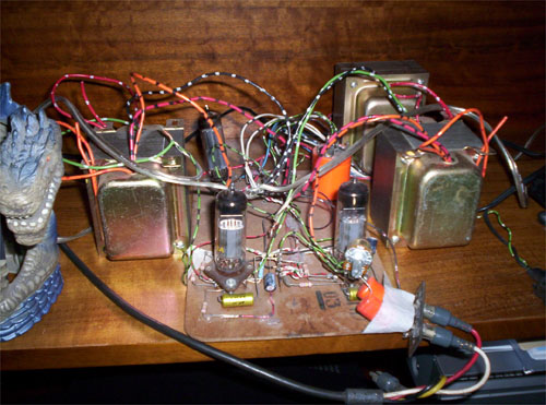
Here is my upcoming tube amp project ( another one! )
It's a 6L6GC single ended, 2 channel amp.The transformer shown is one of the few I wound by hand, it's the power transformer. the outputs, not shown, will come from another amp and are of the closed type.they were also made by hand.
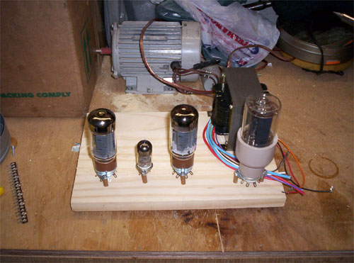
And this is what I'm using to listen to my music since last Dec. it's the 2 channel, ECL82 SE amp. the two outputs are the transformers upside down, orignally designed for the 6L6GC amp above.power trans. is behind them,to the right.
Posted by Mark Gulbrandsen (Member # 72) on 09-28-2005, 12:19 PM:
Thats good work Luciano and Paul! Winding trannys is something I've never done. I've unwound toroids to get the proper voltage on the secondaries but thats actually pretty easy to do.The hard part is taping tham back up with that Kapton tape and boy that stuff is expensive.
Have you run any frequency response or phase tests on these home made trannnies?
MArk
Posted by Luciano Brigite (Member # 1104) on 09-30-2005, 05:55 PM:
The only test I ever meade was connecting them to the circuit and listening to the sound that cmoes out of them.A response test is something I'm always thinking about doing but I'm always laz\y when the time for it comes
I said I was going to post a schematic for the EL34 amplifier I was talking about but still didn't have time to sit and do it nicely.I have it all sketched and ugly. if laziness allows me to do all the things ( finish the 6L6 amp, the schematic,buy parts)I'll run n a pink noise test on the transformers ( along with the circuit) and show it here.
Posted by Will Kutler (Member # 770) on 10-08-2005, 01:45 AM:
Hi Mark
As part of my RCA 816K restoration, I needed to remove the selector switch/oscillator coil assembly as a unit to facilitate a necessary repair to one of the open wafer switch contacts.
Anyhow, the assembly was extermely dusty and dirty, and alot of crap was imbedded in the protective wax used on the many oscillator coils. And all that original wax was nothing more than an oooey gooey mess!
Using a heat-gun on low, I was able to start cleaning up the coils. But I need to recoat them and was strongly considering Q-Dope. Now Q-Dope is rather expensive, and is nothing more than pure polystyrene dissolved in solvents. And polystyrene HIPS is commponly used as an electricaland thermal insulator. Styrofoam is polystyrene. So, what is your take on dissolving Styrofoam in acetone and dipping the entire coil? Or do you have a better suggestion? I am aware of the importance of keeping those coils dry: that depending on how and what they are coated with can eventually cause problems.
Cheers
K
Posted by Luciano Brigite (Member # 1104) on 10-08-2005, 10:43 PM:
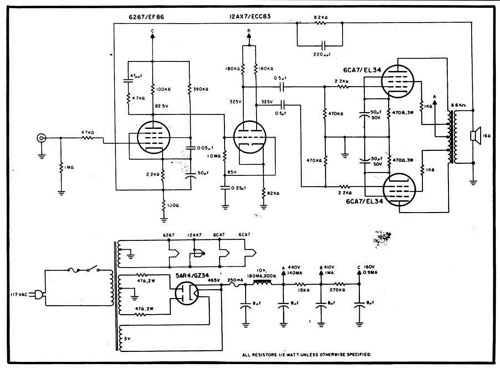
It took a lot more time than I thought to look tru my stuff and find a schematic closer to what I described here in the previous posts.the only thing different in this one is the EF86 in the input and the OPT has only a 16 ohm output. take away the EF86, replace with a ECC82 hooked up for line level and a OPT with a 6.600 ohm primary with screen taps @ 43% from the center tap and 4/8/16 ohm secondary. I wanted to draw my version of it but I'm getting worse and worse in drawing schematics
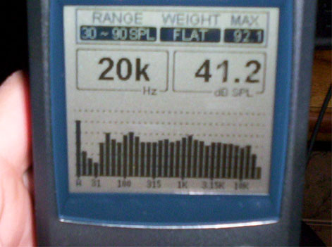
Mark asked about a response test of the transformers, well I hooked my portable RTA to the amp. and fed it with pink noise, this is what I got from the entire system ( amplifier circuit, transformer and speakers):
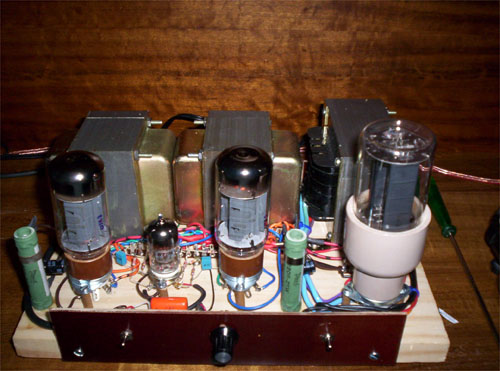
and now this is what I'm using to "make noise" at home .. ( didn't come out as I expected but isn't a total loss either. the power supply output goes way down when the 6L6s heats up and starts working. 5R4 sucks ![[Mad]](mad.gif)
Posted by Paul Trimboli (Member # 1509) on 11-08-2005, 04:48 AM:
Luciano how to do you find your home made transformers? I know most of the factory wound units use interleaved windings, I am guessing you could not do this at home so how do you find their hi end response? What sort of winding rig did you use? Where did you get the core and iron from?
Posted by Paul Trimboli (Member # 1509) on 11-08-2005, 07:56 AM:
Just was reading through the post again and noticed you mentioned that you did interleave the transformer windings, I would be interested to read more about this.
Posted by Bruce McGee (Member # 131) on 11-08-2005, 08:16 AM:
I havent seen a 5R4GY like that in years. Is that NOS?
Posted by Luciano Brigite (Member # 1104) on 11-08-2005, 05:35 PM:
Paul,
I found the interleaved winding easier to do than a normal,continuous winding for primary and secondary.Sure it have it's tricks and since those two transformers shown were the very first ones I made using that kind of winding I got very surprized with the results, and all of them including the power transformer were done by hand, no machines or anything to do the winding, of course they didn't came out in a few hours, took me about a month to complete each OPT and a week for the power transformer.
There is no "esoteric" material in them ,enameled copper wire is the kind used in most of consumer transformers and the iron is of standard laminated steel ( not the GOSS kind wich costs a lot more) insulation between the primary/secondary layers are done with off the shelf white paper and the bobbin (winding core) is the formed plastic. the lamination is not crossed ( like E-I,I-E, a little hard to explain it on text only)but stacked with all the "E" to one side and the "I" to other and a piece of paper or plastic between them for the core gap since it's a single-end OPT. From what I could see with htese transformers, the frequence response is based on the core size ( for low to mid frequencies) and hte number of interleaved windings (for low to high frequencies) a bigger core gives more bass and more interleaving,mids and highs. sure it has limitations and after some point it doesn't do any better to any side and makes things only more expensive and complicated.
The interleaved winding design I did in these transformers were based on information from the " radiotron Designer's Handbook,4Th edition" and also from taking the covers off of a transformer and taking a look at how the winding was done of course *without* disassemble the whole transformer and undo the winding,most of them will show where the windings starts and ends and wich one is primary and secondary. Mine has a primary in 10 layers connected in series interleaved with 8 secondaries in parallel.finding out wich wire to use in hte secondary is one of the tricks here, since it has to be done in one layer htat'll fill the heigt of the plastic core without leave an empty space at the end of the turns nor overlap them to complete the requested number of turns.
the same number of primary turns in each layer is also important.
I have two other OPTs on the way,htose however went in halt mode because the secondaries doesn't fill the entire heigh,messing up with the next primary layer. when time allows me, I'll get back to them,redo the winding math to fit the core I selected and take pictures of how they're being done. ( I'm extra busy with theatre work this month,but I'll have something about them as soon as I can)
Bruce,
that one is a JAN 5R4WGA and yes, it's a NOS, made by Chatham,in 1956 if I remember it right. I have some 3 more of those somewhere along with some 5Z3.
Posted by Phil Hill (Member # 371) on 11-08-2005, 05:43 PM:
Hiya L!
You might wanna post an accurate schematic as to what you built as the above one is a pretty crappy design...it's riddled with poor engineering.
Also, I'm sorta disappointed at the BIG dip at 31 Hz, but without a true representation as to what you've built, we cannot actually comment on it.
While the 5R4 is a great tube for SOME applications, it's not for what you're using it for. At the very least, a 5AR4 would be better.
Bruce: There are plenty of 5R4WGB ruggedized rectifiers with the hi-temp base and thick glass envelope available.
Posted by Mark Gulbrandsen (Member # 72) on 11-09-2005, 08:03 AM:
Phil,
You've got it all wrong.... Even those ruggidezed 5R4 rectifier tubes are weaklings compared to a decent mercury vapor rectifier tube. Aside from handling a ton more current they also look way cool!
Mark
Posted by Luciano Brigite (Member # 1104) on 11-10-2005, 07:24 PM:
The dip at 31Hz is a mistery to me ,no idea why it's happening. hte only thing I can relate to it is that while doing the math for core sizes,a work frequency is requested and I have used 30Hz for every OPT I calculated..
I got the 5R4WGA along with a lot of oddball tubes, most of them seems to be lo power transmitter tubes ,some Russian tubes and a few Philips SQ tube types.there are some mercury rectifiers in the boxes,but I have yet to find a place with tech data for them
( and before that, the list with the tube codes. )
My intention was to use a 5U4 and not the 5R4..
Posted by David Buckley (Member # 2600) on 11-11-2005, 12:10 AM:
The 31Hz dip, does your RTS allow you to measure the amp output electrically? Have you tried the two channels independently? Could be a room thing, or height of speakers off floor...
Posted by Luciano Brigite (Member # 1104) on 11-12-2005, 06:26 PM:
David,
my RTA can read frequency response electrically ( balanced line level),I have to make a connection cable for this use, since it doesn't come with any.
The test I showed was made with both channels at same time, fed by the RTA's generator and sampled by it at a distance of about 4Ft from the speakers.Those aren't big speakers and are in my computer desk's shelf.
It still surprizes me because,for me, the bass response is performing well.
Powered by Infopop Corporation
UBB.classicTM
6.3.1.2