This is topic Old telephone plugs. in forum Film-Yak at Film-Tech Forum ARCHIVE.
To visit this topic, use this URL:
https://ft-forum.com/ft/cgi-bin/ubb/ultimatebb.cgi?ubb=get_topic;f=8;t=005731
Posted by Stephen Furley (Member # 1277) on 03-01-2009, 02:48 PM:
I'm looking for two old style four-prong American telephone plugs. They need to be proper re-wirable plugs, not moulded on ones, or modular adapters. Does anybody have any they don't need, or know of any shops that might have some old stock still sitting on the shelf, or even any telephone collectors' clubs or similar that might know where to get hold of some?
Posted by Scott Norwood (Member # 30) on 03-01-2009, 06:23 PM:
Try Phoneco. They don't list them on their web site (or at least I can't find them), but they might have some or know where to get them.
I don't know if this connector has an actual name. Normally, only two conductors are used. The yellow wire is sometimes needed to control ringing on party lines. More commonly, the black and yellow wires can be used for a second line, to provide A-lead control for a key system, or to allow a transformer to power the dial light on Princess and Trimline sets.
Posted by Jim Cassedy (Member # 4115) on 03-01-2009, 06:49 PM:
Stephen- I live in a very old house (1920's) and still have two dial phones wired up to those old style 4-prong plugs & jacks.
Here in the USA, I used to be able to buy them at Radio Shack, but I'm not sure they still carry them since I haven't needed one in years.
I do know for sure they still carry a female modular (RJ-11) to 4prong plug adapter for about $6(US) I don't know if they still carry the jacks.
I know American telephone parts manufacturer ALLENTEL discontinued making the actual plugs & jacks several years ago.
Scott- You are generally correct in your description of the various uses for the 3rd wire in US telephone systems, but I beleive the Britsh Telco still uses a 3 wire system. Two wires carry the "voice" current, and the 3rd is used for ringing.
The loop drop is brought to the house in a 3-wire configuration, and the the first connector block or jack contains a capacitor to convert the 3-wires to a 2 wire system.
The rest of the jacks on the premisis are wired to the first jack using two wires, but many of the older BPO telephones still use 3 wires for the ringer to work. (or you just need to wire a capacitor inside to pass the ringing current to the bell)
But Stephen is probably more of an expert on the British system than I am. I worked as an engineer for Pacific Bell for about 10 years and that 4 prong plug and jack did have a name, but I'll be darned if I can remember what the official telco designation was. Maybe I can find it in one of my old Bellcore documents. (Just for fun!)
Posted by Scott Norwood (Member # 30) on 03-01-2009, 07:09 PM:
I looked it up. The plug is a 283B (square) or 505A (round). The jack (female) is a 391A, 548A, or 549A. (According to BSP 461-630-100). Apparently, Phil and I are not the only ones here who collect phone stuff.
Posted by Stephen Furley (Member # 1277) on 03-02-2009, 06:05 AM:
Phoneco have got them listed, on the second accessories page. I hope they've still got some in stock; I'll give them a call this evening.
It doesn't say if they accept orders from overseas.
quote: Scott Norwood
Apparently, Phil and I are not the only ones here who collect phone stuff.
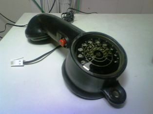
Some very grotty pictures taken with my mobile 'phone, in the frame room with no proper light in it at the moment, due to building works:
GPO Engineers Telephone 280 Mk.2 1950s, still in use in the '80s
Here is the modern version, a Tempo DSTS-2, hanging on, and connected to, the frame at work:
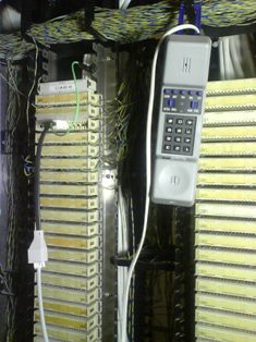
The adapter cord is from a standard British telephone plug to a special test plug to fit Krone connection strips. When you insert the plug it breaks the connection at that point, and by turning the plug over you can connect either towards the equipment, or towards the cable, which can be useful if you're injecting tone from the far end. There's a slightly different plug where the two sides are connected together, so you can insert it without breaking the connection between the user's telephone and the equipment.
The green wire clipped onto the metalwork of the frame is an earth connection to enable earth recall to be used. Most of our analogue telephones still use earth recall, but in a couple of areas where analogue circuits are patched through voice panels and Cat. 5 cables to RJ-45s in rooms there is no earth connection available, so TBR has to be used.
This is the whole frame:
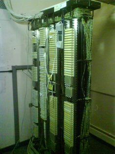
The frame is much bigger than it needs to be; the right hand side in the picture is connected to the equipment, and the left side out to the telephones around the building. Looking at the equipment side, each of the cream-coloured Krone strips can hold 10 pairs, there are 20 of them in each of the four large blocks, so that's 200 pairs in each block, or 800 in this part of the frame. There's the same again round the back on the other side of the frame, so in theory we could have 1600 pairs going to the equipment, and about the same going out to the 'phones. We don't have anything like that number, maybe half of it.
[ 03-02-2009, 07:52 AM: Message edited by: Stephen Furley ]
Posted by Rick Raskin (Member # 1561) on 03-02-2009, 08:09 AM:
Stephen:
I have 2 of the plugs and one jack if you are still interested.
---Rick
Posted by Stephen Furley (Member # 1277) on 03-02-2009, 12:29 PM:
Jim,
You're on the right lines, but not quite there. It's two wires into the building to the first socket, but three, or four wires from there to the other sockets, and the 'phones use three, or four wires.
Until the early '80s the GPO (Post Office) had a monopoly on providing public telephone service, except in the city of Hull for some reason. You couldn't by a telephone to connect to the PSTN, you had to rent them from the GPO, along with your line. Most telephones were hard wired to a small junction box on the wall. Since sometime in the '40s when the 300 series was introduced it has been possible to have a telephone with the bell internal; before that it was housed in an external bell-set. These bells were low-impedance, 1k Ohm, and were wired in series when more than one telephone was installed on a line. This made thins rather complicated, as the master telephone, intermediate extensions and last extension all had to be wired differently. It was not common, but it was also possible to have extensions connected via a plug and socket, the so-called 420 plug, which was rather like a quarter inch audio jack plug, but shorter and fatter, with four sections. This made things even more complicated, as there had to be a switch contact inside each socket to short out the bell connection on that socket when the plug was removed. When the GPO had the monopoly this wasn't too much of a problem, as a GPO engineer would consult his 'N-Diagrams' which told him how to configure each 'phone, and then he wired the whole thing up.
With liberalisation, with people able to just buy telephones in shops, and plug them in this wasn't going to work. What happened was that the GPO retained the monopoly of supplying the line, and terminating it at the master socket. The owner of the building could install their own wireing from this point, but were not allowed to connect directly to the GPO wireing, they could only plug in to it. A special master socket was later introduced with a removeable front section containing punch-down terminals to which the user could attach their own extension wireing, and the front section could then be plugged into the socket contained in the rear part. If you report a fault to BT you will usually be asked to remove this front section, thereby isolating your own wireing from BTs, and plug a telephone directly into the socket behind; if this works then it's not BTs problem.
A new style of plug was introduced at this time, it has six positions, but usually only four conductors, like a RJ-11, but somewhat larger, and with the latch on the right side, like the one attached to the old test telephone in the picture I posted. I believe that this connector was chosen specifically to stop people plugging in un-approved foreign equipment. It's a nice connector, I prefer it to the RJ-11, but I think I would have accepted the latter, in the cause of standardisation.
At this point a silly decision was made, rather than put the line on the centre pair, (3&4) as on the RJ11 it's on the next pair out, (2&5). The master socket contains the bell capacitor, connected between one side of the line, pin 2 I think, and pin 3. It also contains a surge arrestor connected across the line, and an out of service resistor to enable the line to be tested when there's nothing plugged into it. Secondary sockets for extensions have none of these components, and simply have pins 2,3,4 and 5 connected in parallel with the master socket. Pin 4 is used for earth recall on some PABX systems, and pins 1 and 6 are not normally used. The bell was changed to a high-impedance (4k Ohm) one, so that all bells could be connected in parallel. This meant that all telephones could be wired the same, and any telephone could be plugged into any socket. Since the telephone has the bell connected to pin 3, a British telephone would not ring if connected via a BT to RJ-11 adapter in America, it would only ring if there was a British master socket in the circuit somewhere. You can now get adapters which have an internal capacitor to solve this problem.
With the demise of traditional bells, and telephones going all-electronic, some newer telephones simply detect the ringing signal on the line, and do not need to use pin 3 to ring.
That's about it, long story, and done for what seemed like good reasons at the time, but with hindsight I wish we'd done the same as the rest of the World.
There was a version of the plug listed with the latch on the left, which was supposed to be used for handset cords, but I've never seen one, I don't know if they were ever made. These days handset and line cords are attached to telephones via sockets, RJ-11 for the line, and the smaller 4-pin one for the handset, as elsewhere in the World. This is where the silly decision to put the line on pins 2&5 comes back to haunt us. Telephones for use in the UK either have to have the RJ-11 socket wired this way, with the line cord wired straight through, or they have to have the line on pins 3&4, as they would be elsewhere, and use a special line cord with the inner and outer pairs crossed over. Most use straight cords, but we have some, even the same make, which need crossed ones. Crossed cords are often needed on things like fax machines, and they're a pain to make, as there's not much room inside the plug to cross the wires over.
[ 03-02-2009, 05:08 PM: Message edited by: Stephen Furley ]
Posted by Mike Schindler (Member # 1309) on 03-02-2009, 01:22 PM:
I never realized that there were phone geeks out there. My grandpa was actually the co-inventor of the modern phone jack.
As I understand it, there was another guy who worked for the phone company who was an engineering genius, but he didn't have a high school diploma, so he was only able to go so far in the company. But he pitched the idea to my grandpa, who was a higher-up, and my grandpa liked it, and took it to his supervisor.
The supervisor thought that it wasn't worth putting resources towards development on the project, but told the two of them that if they wanted to work on it after hours, he'd pay for their dinner.
So they did, and the modern phone jack is the result, and that's why Stephen's having so much trouble finding his four-prong plugs. ![[Wink]](wink.gif)
Posted by Stephen Furley (Member # 1277) on 03-02-2009, 01:41 PM:
Rick, I'll send you a private message later this evening.
Mike, so when was the RJ-11 first introduced for telephones over there? I first saw them used for serial ports on an early 16 bit computer, sometime in the '80s. It was a considerable advance on most of the old telephone connectors in use around the World.
I really must get a digital camera; the one in my 'phone is useless, and I don't have time to develop and scan film this evening.
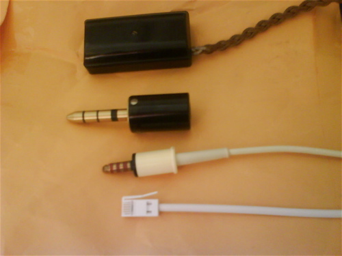
From bottom to top, a standard British telephone plug, a 420 type plug from the '60s, a 404 type, a design probably dating from the '20s or '30s, though this one was probably made in the early '50s, and a fixed connection box of similar vintage. The older plugs were not common, most telephones were hard wired at that time. The 404 is huge, and very heavy, there must be several ounces of brass in this thing. Inside the Bakelite cover there's a solid bock of brass with four slots milled in it to take the wires of the braided, cloth-covered cord, as seen above it. To give an idea of scale, the connection box is about 100 mm, four inches, long.
I've never actually seen the socket for the 404, somebody has a plug and socket pair on Ebay at the moment for 75 pounds! I think I'll give it a miss.
Posted by Mike Schindler (Member # 1309) on 03-02-2009, 02:11 PM:
Actually, I just asked him that the other day, and he said he didn't remember exactly, but he thought it was sometime in the late 70's. Obviously, there was a fairly long testing period involved, but I think he retired around 1983, so it would have to be before then.
Posted by Stephen Furley (Member # 1277) on 03-02-2009, 02:44 PM:
Scott,
I've just been looking at the Phoneco site; It looks very similar to Telephone Lines in Cheltenham were I got my old 280 engineers 'phone from. They have three floors packed with thousands of 'phones, just like one of the pictures on the Phoneco site. web page
The old plugs don't seem to die out; I'm told that the 420 is still used, alongside the RJ-11, in India, and the American four prong is used in Korea and Saudi-Arabia. This site lists no less than five types for Germany.
I mentioned the 'N-Diagrams'. These were something of a work of art, all the text on them was very neatly hand-written, and the pictures were hand-drawn. Many of them are available here:
For example, suppose you were a GPO engineer going to install a 706 telephone, something quite similar to the American 500, in the '60s or '70s. N806 would tell you how to to connect up he telephone internally for various different configurations, if you needed to install extra parts, mainly switches, in it then N808 would tell you about those, and 809 about the buttons to operate them. For the slightly later N746 'phone you'd need N846, N848 and N849. The various ways that telephones could be installed were known as 'plans'. One common way of connecting fixed extensions was Plan 1A, covered by N4502, and if you also wanted portable plug-in extensions that was covered by Plan 4, N4520. These N-diagrams covered all equipment, right back to the early wall-mounted wooden telephones. They really are very useful for collectors trying to get old equipment working again. I received some parts in the post today, and I'm just about to convert a 746 telephone into a Plan 4 portable extension with a couple of extra switches and a special line cord.
[ 03-02-2009, 04:17 PM: Message edited by: Stephen Furley ]
Posted by Stephen Furley (Member # 1277) on 03-03-2009, 04:45 PM:
Rick is kindly sending me some plugs, and I'm going to try to get a couple more, and at least one more 'phone, from Phoneco. Now I've got a problem; what are the pin connections on these plugs? I've never seen one wired up that I can copy. Are the colours in the line cords of these older 'phones standardised, if so what are they? Both of my American 'phones are in a storage place at the moment, so I can't look at them. I'll probably get them out at the weekend, so I can fit the plugs when they arrive.
How do you refer to the wires in the line over there; do you call them 'Tip' and 'Ring' or 'A' and 'B' wires, or what? I want to make sure I get the polarity right.
Posted by Rick Raskin (Member # 1561) on 03-03-2009, 05:24 PM:
When dealing with telephone sets Tip & Ring are most common today. Older applications additionally used the sleeve lead. I'm not sure, but one of the plugs I sent may have the standard R,G,Y,B wiring inside.
From Wikipedia:
Modular connectors were originally invented and patented by Bell Telephone Laboratories (patent filed 6 July 1973; U.S. Patent 3,860,316 issued 14 January 1975), and replaced the hard-wired connections on most Western Electric telephones around 1976. At the same time, they began to replace screw terminals and large 3 and 4 pin jacks in buildings.
Posted by Scott Norwood (Member # 30) on 03-03-2009, 06:32 PM:
Red is ring and green is tip. If the set doesn't ring but otherwise works, tie yellow and green together. Polarity normally does not matter, except with early-model Touch-Tone sets, where the dial would not work if the polarity were reversed.
In the US, the ringing signal is 90VAC at 20Hz. I assume that the UK uses a more-or-less identical ringing scheme. If not, you may need to modify the set in order to make it ring properly.
Posted by Stephen Furley (Member # 1277) on 03-03-2009, 07:49 PM:
Scott,
This page gives it the other way round, red for tip and green for ring for line 1. Has he got it the wrong way round? Here tip is red and ring is white for cords, with blue for bell and green for earth, though old phones used blue for earth. If I just take the tip and ring wires and connect these to the jack, and ignore the bell wire, then it should work.
British ringing current is 75V a.c. 25Hz, 0.4s on, 0.2s off, 0.4s on 2s off, I think I've got those times right, it's something similar to that anyway, to give the characteristic Brr-Brr Brr-Brr double ring that we have here, so the 'phones won't sound right when they ring,but it should work.
There's also a difference in dial pulse trains as well, ours are 67% break, 33% make but I think yours are 60% and 40%, but I'm sure it will be close enough; if you can dial by just tapping the hook switch then it can't be that critical.
Which pins on the four prong plug are used for tip and ring? How should the jacks be mounted; so the cord comes out of the plug downwards?
There's something else odd over here; the official standard for the plugs numbers the wires from left to right, whereas BT number the jacks the other way, starting from the latch side. You seem to have an over-complicated electrical system, and we have an over-complicated telephone one.
I think it was you that mentioned the telephone with the illuminated dial. We can go one better than that, we had a 'phone with an illuminated dial which didn't need a transformer, or extra wires; it was radioactive! It actually contained a tube of radioactive gas behind the dial. This wasn't to much of a problem for a user with one or two 'phones, but when BT came to scrap several thousand of the things they found themselves with a considerable quantity of radioactive waste on their hands.
This was the Trimphone, There are pictures of them on
this page
On the same page the 706 and 746 are pretty much like your 500, and if you look at the page with the older models, the 300 series was similar to your 302, though made of Bakelite, rather than metal or thermoplastic. The 200 series was pretty much equal to the WE 202, though a different shape. On the Phoneco site the AE 80, I think that was the number, is also rather similar to our 706. Other than special ones for things like hazardous areas and outdoor use, we haven't generally had metal telephones here since the Candlesticks, in the '20s. The Bakelite ones are very heavy though.
Posted by Scott Norwood (Member # 30) on 03-04-2009, 08:00 AM:
I don't know about the correct orientation for a 4-pin plug, but there are adapters to convert this to RJ11, so it would be easy enough to figure out if someone has one of these adapters. In an RJ11 connector, the center pair (pins 3 and 4) is tip and ring, but I can never remember which pin is which.
Our ringing cadence is 2 sec. ring, 4 sec. silence, which was supposedly designed to be annoying enough to get people to answer the phone (and, thus, generate billable calls).
It sounds as if your ringing voltage is close enough to ours that most phones will ring just fine (but sound wrong). You can get a ringing freqnency generator (the Western Electric 118A is commonly available on ebay) if you want it to sound right. In the US, a normal line is supposed to support a REN of 5 (i.e. it can ring up to five 500-set ringers, and often more if the CO is nearby). This is a problem with many VOIP ATA devices, which often support much lower RENs and can thus be difficult to interface with a house full of telephones.
Newer sets with lighted dials use LEDs and can be powered off the line current. The transformers were needed for older sets. If you use a transformer, be sure that you do _not_ connect a set that is wired for A-lead control to the same line, as it will short the yellow and black pairs and either blow a fuse or burn down the house.
It's interesting that your telephones are so similar to ours, yet different enough to be distinctive. The 2500 set is still quite common here, particularly in commercial buildings, but rotary sets are rare.
Posted by Stephen Furley (Member # 1277) on 03-05-2009, 05:51 PM:
The maximum REN over here is 4. Most 'phones, including converted old-style ones, have a REN of 1. If they weren't converted they would be 4. Some of the older modern ones were higher than 1.
quote: Scott Norwood
It's interesting that your telephones are so similar to ours, yet different enough to be distinctive. The 2500 set is still quite common here, particularly in commercial buildings, but rotary sets are rare.
That's why I decided to get US 'phones for the couple of foreign ones which I've got, rather than, say, French ones; there's an equivalent to each standard model, and they make an interesting comparison.
Scott, I've sent you a private message.
Posted by Stephen Furley (Member # 1277) on 03-11-2009, 04:33 PM:
Scott, I sent you a private message last week, but it's status is still unread; please check your private messages.
Powered by Infopop Corporation
UBB.classicTM
6.3.1.2